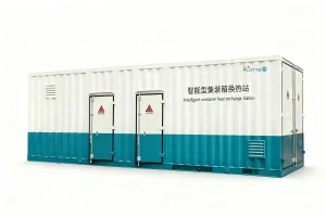
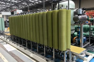
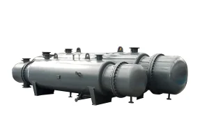
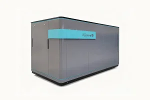
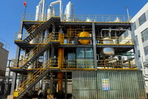
High-precision industrial heat exchange equipment designed and engineered by Flotte Energy Saving Company.
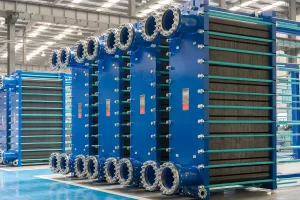
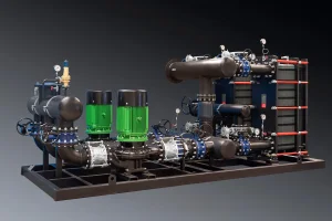
In modern industrial thermal design, calculating the required heat transfer area of a Plate Heat Exchanger (PHE) is a critical task. It dictates not only the operational efficiency of the system but also direct capital expenditures (CAPEX) and long-term operating costs (OPEX). A miscalculation in the heat exchanger area can lead to insufficient thermal transfer or unnecessary high pressure drops, resulting in excessive pumping power demands.
The heat transfer area ($A$) is directly influenced by the heat duty ($Q$), the overall heat transfer coefficient ($U$), and the Logarithmic Mean Temperature Difference ($\Delta T_{lm}$). At Flotte, our engineers leverage three decades of experience to compute this area using state-of-the-art computational fluid dynamics (CFD) and rigorous thermodynamic models. This ensures that every plate profile and chevron angle matches the precise requirements of the target application.
"Precision thermal dimensioning is not just about choosing standard sizes; it is about simulating the dynamic boundary layers under localized shear forces to prevent fouling while optimizing the heat transfer rate."
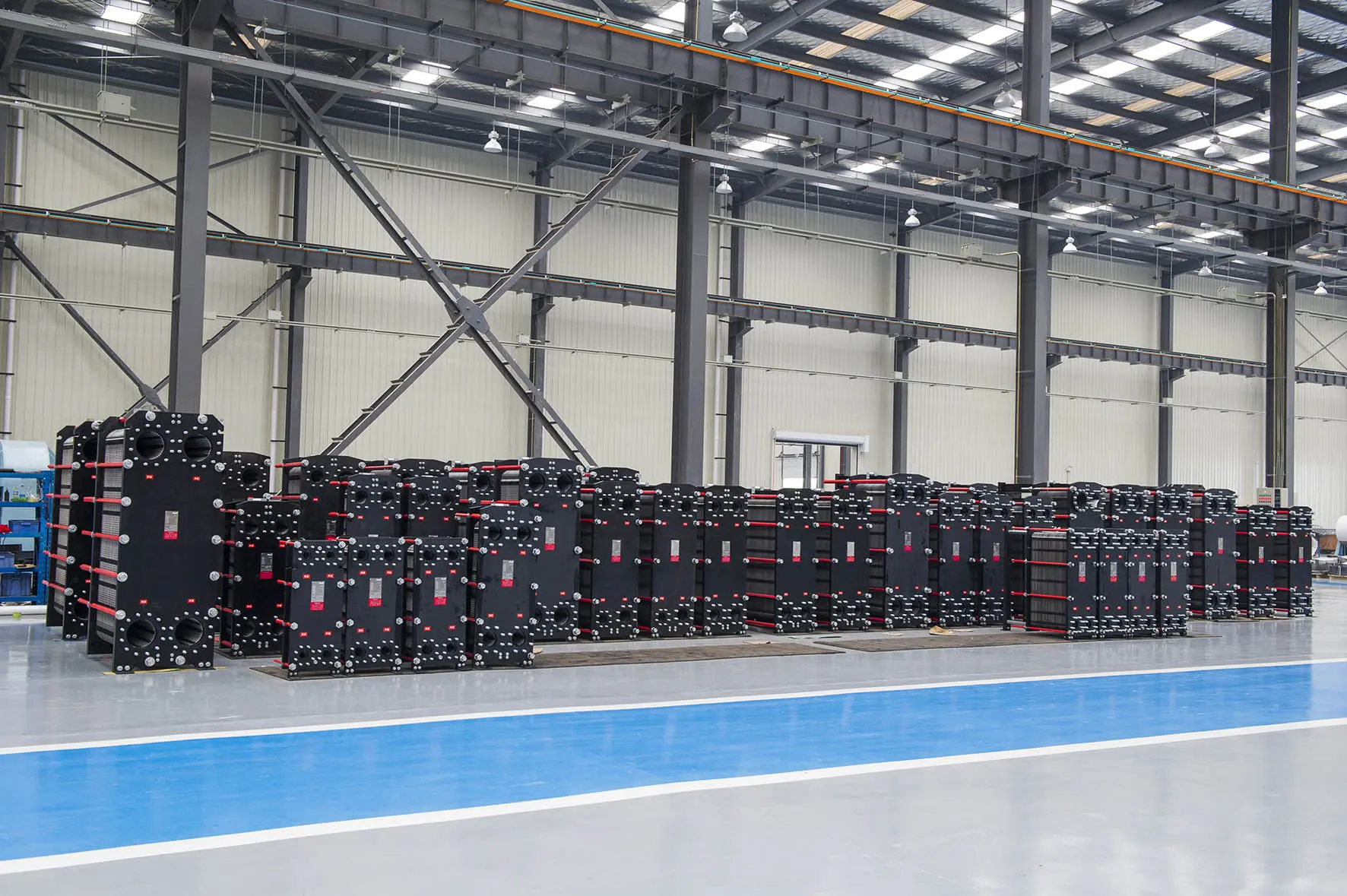
How thermodynamic efficiency drives industrial operations globally.
With global regulatory bodies mandating strict energy reduction policies, industries in Europe and North America are focusing heavily on heat recovery. Optimizing the heat exchanger area calculation is essential to recoup waste heat from industrial effluent, cutting down overall carbon intensity.
Titanium, nickel alloys, and high-grade stainless steel (SS316L) prices are highly volatile. Accurate area sizing ensures that no excess material is utilized, keeping procurement costs minimal without sacrificing the structural integrity under high pressure.
Modern cities are moving toward Fourth Generation District Heating (4GDH) systems, requiring low-temperature operation. Precise heat transfer area calculations allow systems to function effectively even with minimal thermal gradients, boosting district energy efficiency.
The scientific approach to calculating Plate Heat Exchanger Area.
Calculating the required heat exchange surface area is governed by the fundamental heat transfer relation. To design a plate heat exchanger, engineers must calculate the total heat transfer area ($A$) using the formula:
The Logarithmic Mean Temperature Difference ($\Delta T_{lm}$) is determined based on the temperatures of the hot and cold fluids entering and leaving the unit:
The calculation of the **Overall Heat Transfer Coefficient ($U$)** is more complex as it accounts for the individual convective heat transfer coefficients of the hot fluid ($h_h$), the cold fluid ($h_c$), the plate material thermal conductivity ($k$), the thickness of the plate ($t$), and the fouling resistances ($R_{fh}$ and $R_{fc}$):
In practice, the convection heat transfer coefficients ($h$) are highly dependent on the **Nusselt Number ($Nu$)**, which correlates fluid velocity, turbulence, and plate corrugation. High chevron angles (often referred to as hard plates) produce high turbulence and high $h$ values, but they also result in a corresponding spike in pressure drop ($\Delta P$). Conversely, low chevron angles (soft plates) minimize pressure drops at the expense of heat transfer efficiency.
The shift towards AI, micro-engineered surfaces, and smart sizing systems.
Traditional heat exchanger calculations rely heavily on empirical safety margins. Today, AI-powered thermodynamic modeling simulates real-time variations in viscosity, thermal conductivity, and fouling coefficients to optimize the number of plates precisely.
Innovations like Flotte's patented **Plate Heat Exchanger Scale Removal Device** drastically lower the fouling resistances ($R_f$). Maintaining cleaner surfaces means the design area can be optimized without incorporating oversized margins for hypothetical fouling.
Modular frames allow quick expansion of the heat transfer surface area when capacity requirements increase. By installing spacers and extension bolts, factories can increase heat exchanger capacity without purchasing completely new frames.
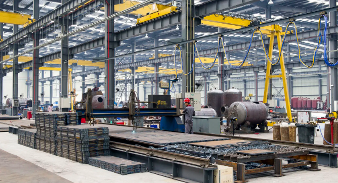
Established in 2013 with a registered capital of 101 million yuan, Flotte Energy Saving Company trace its technical origin back to Flotte Thermal Engineering founded in 1995. Over three decades, our engineering teams have pioneered breakthrough innovations in HVAC systems, municipal water equipment, and water treatment solutions.
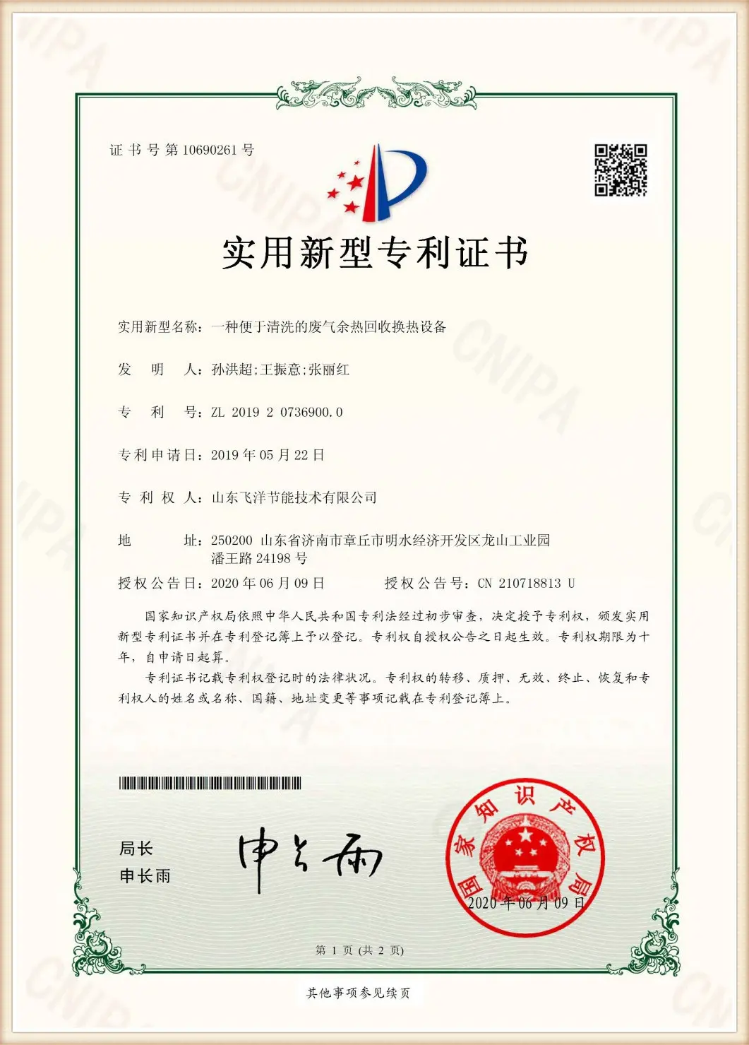
Our commitment to thermodynamic perfection is backed by numerous patent certifications, including patents for the "High-Efficiency Plate Heat Exchanger", "Intelligent Plate Heat Exchanger System", and the "Plate Heat Exchanger Scale Removal Device". We maintain rigorous compliance across globally recognized frameworks: ISO9001:2015 Quality Management System, ISO14001 Environmental Management System, and ISO45001 Occupational Health and Safety Management System.
With a comprehensive R&D center and state-of-the-art diagnostic laboratories, Flotte guarantees the thermodynamic parameters stated in our technical designs are fully validated. Every unit leaving our factory is built to operate under demanding peak loads with minimum maintenance overhead.
From raw metal coil to high-performance gasketed heat exchanger assembly.
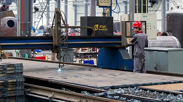
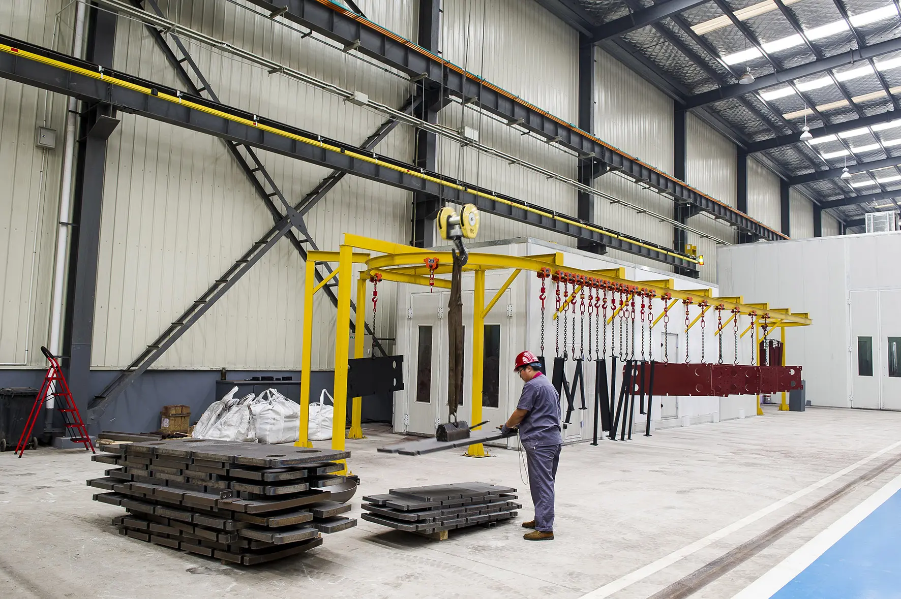
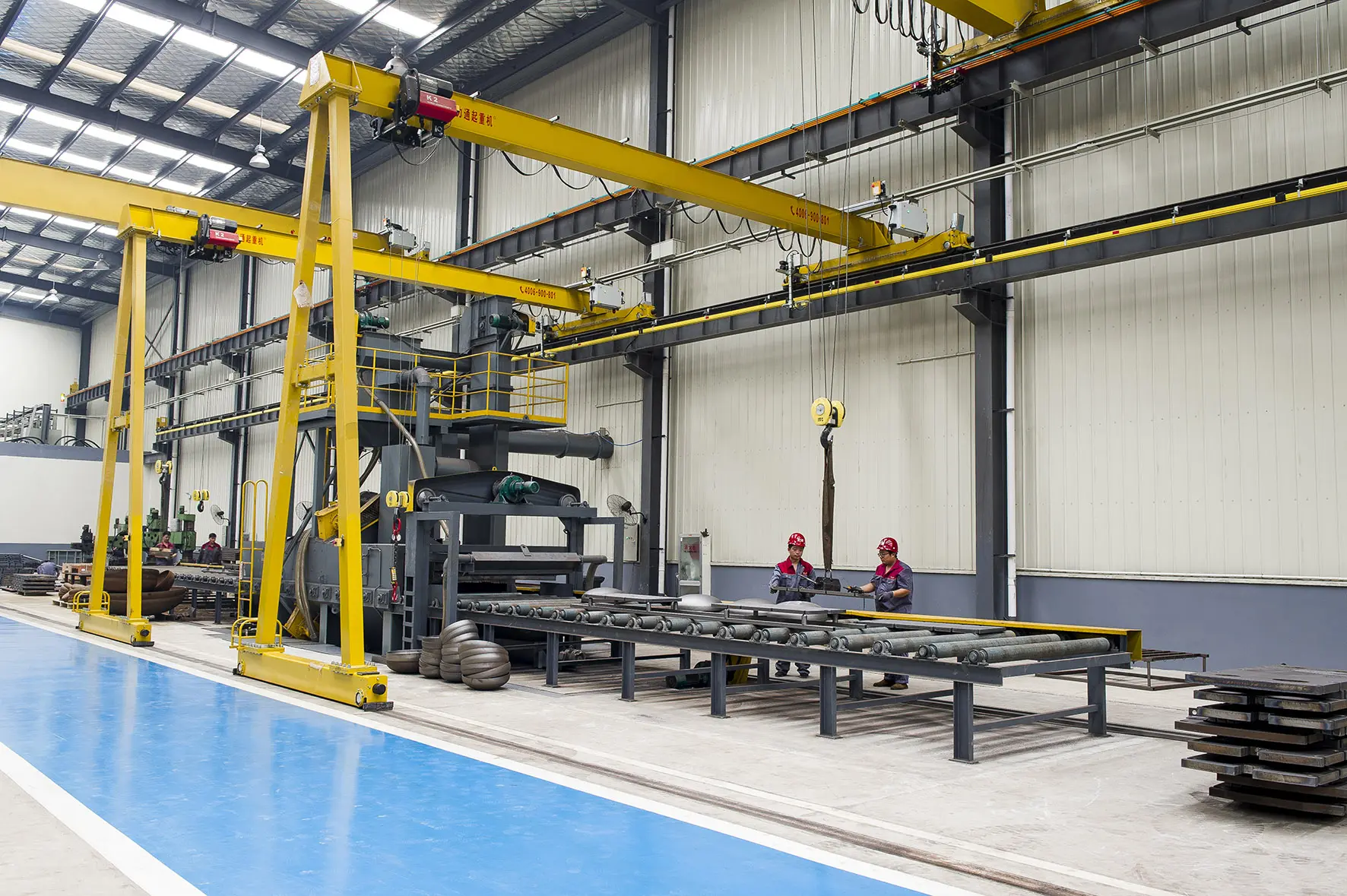
Laser cutting and machining of heavy clamping frames to ensure exact dimensional accuracy under high operating pressures.
High-precision micro-forging applied to reinforcing critical stress distribution zones on the frame and locking bolts.
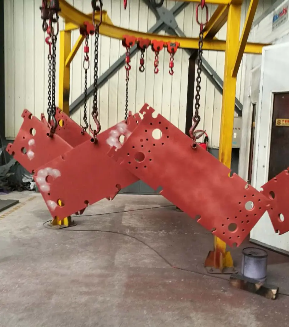
Anti-corrosion coating application to ensure resilience against marine environments and harsh industrial atmospheric exposures.
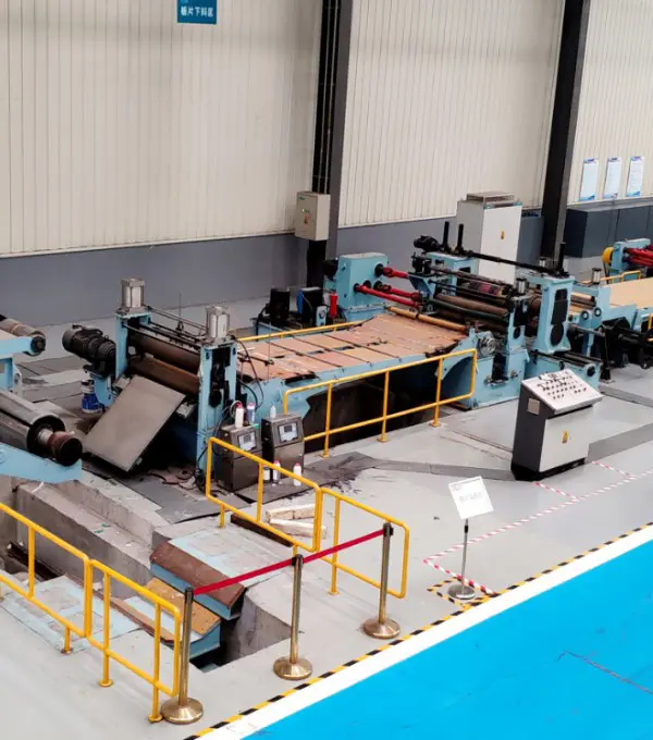
Automated shearing of stainless steel/titanium sheets followed by trace-code marking for complete life-cycle material tracking.
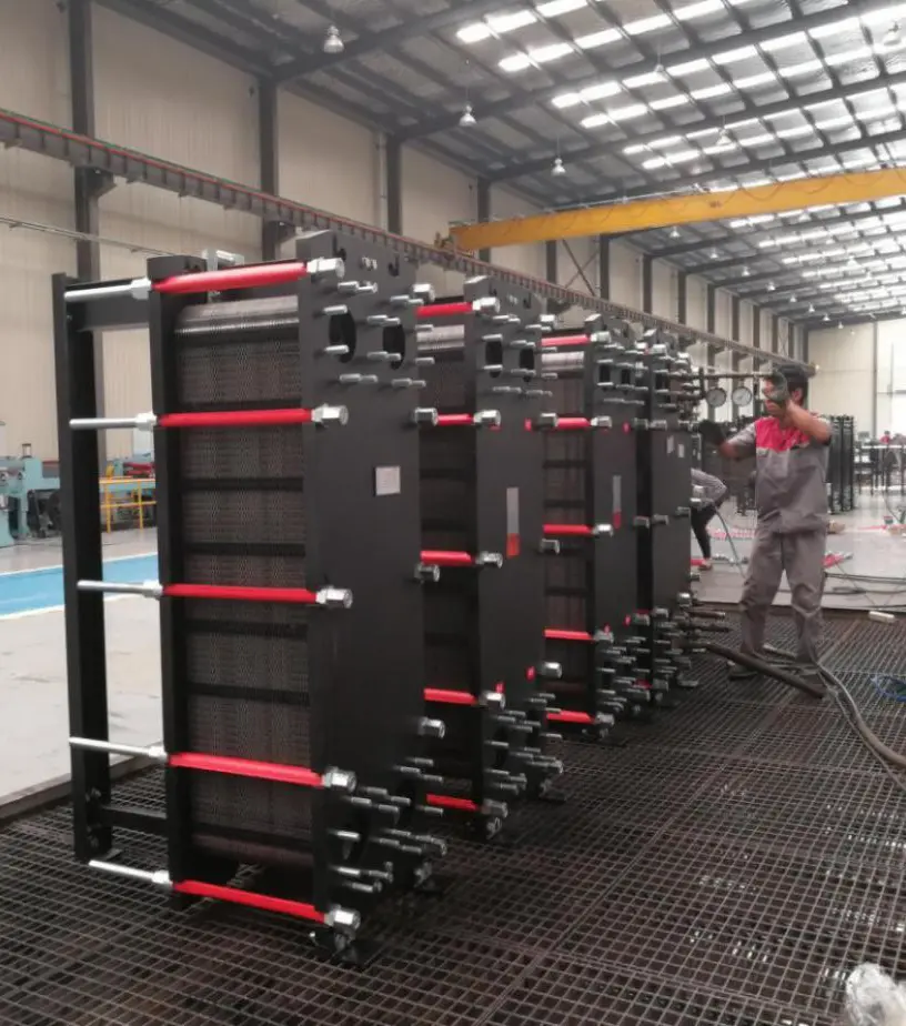
Hydrostatic testing up to 1.5 times the design pressure limit to guarantee zero leakage and cross-contamination.
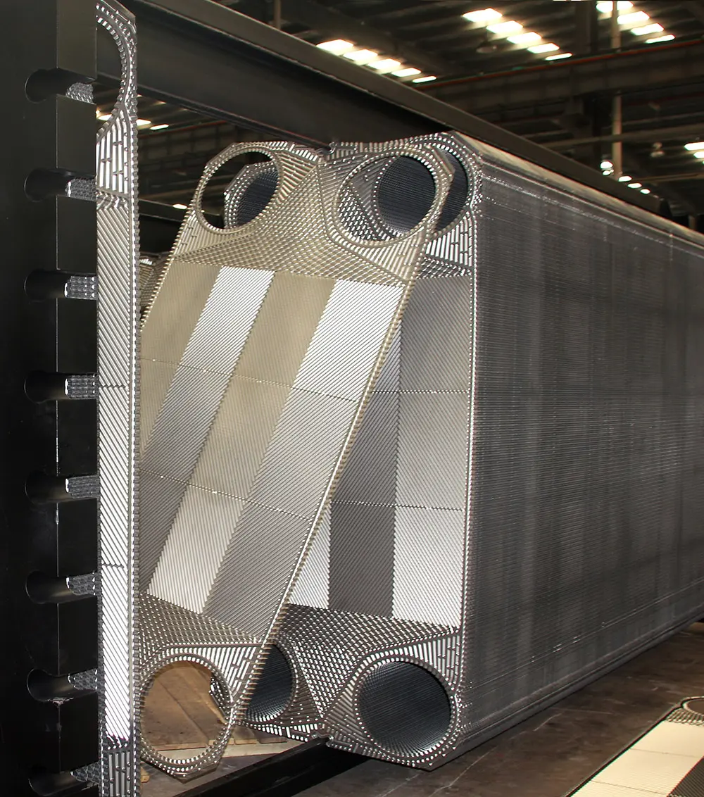
Hydraulic compression of the plate bundle to lock plates and gaskets into perfect parallel alignment.
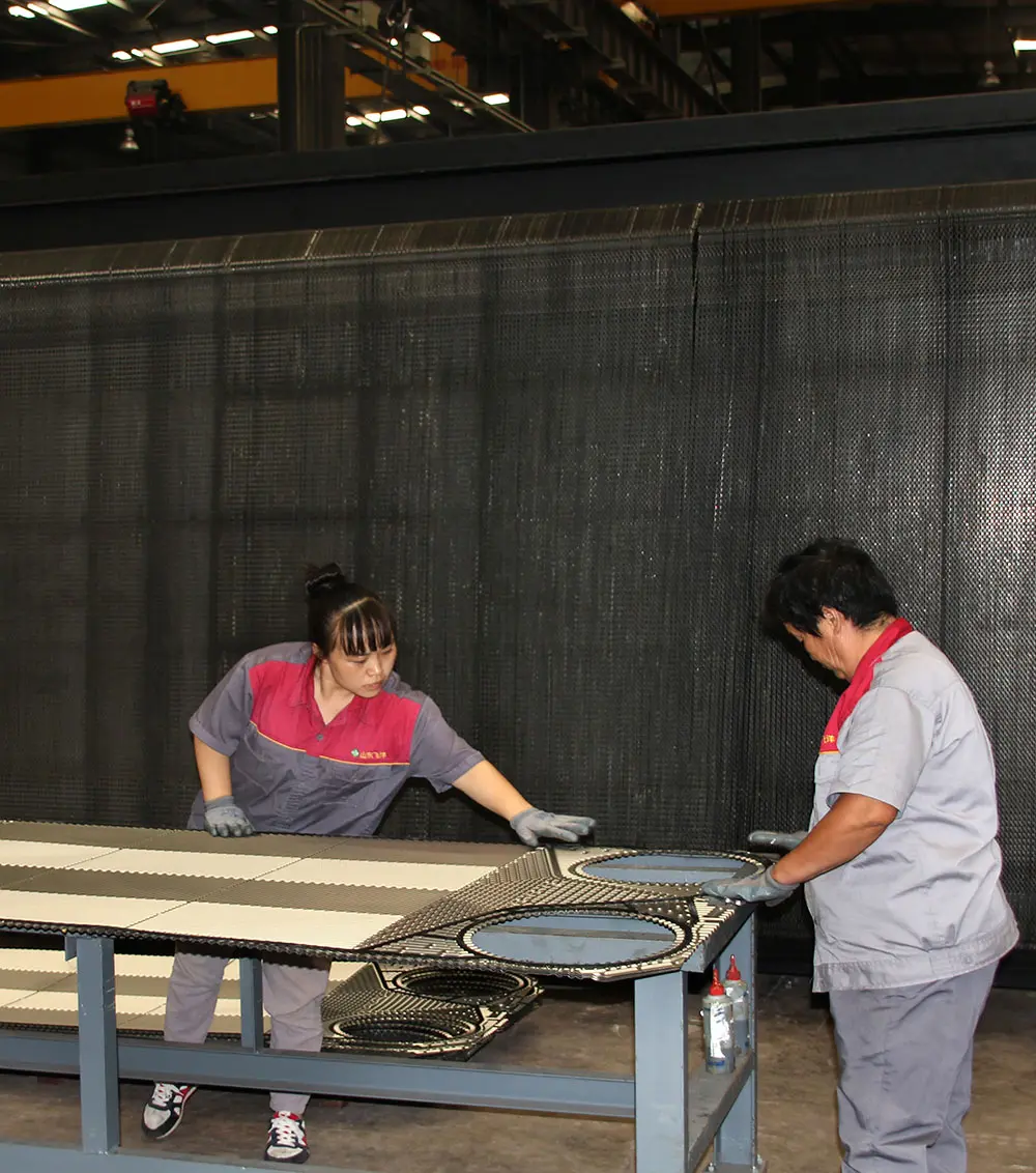
Precisely cured EPDM or NBR rubber gaskets optimized for thermal cycling resistance and positive sealing interfaces.
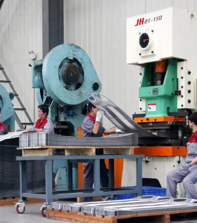
High-speed punching of fluid distribution ports on plates using precision CNC stamping tooling lines.
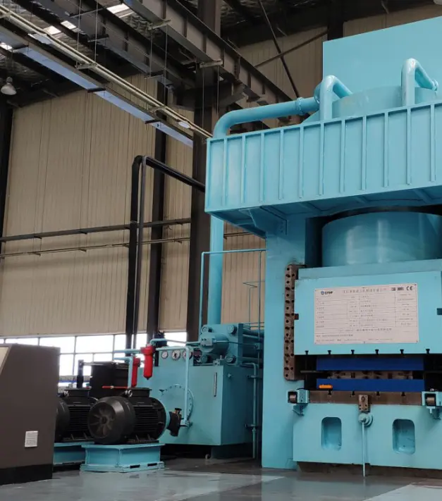
Massive hydraulic presses (up to 20,000 tons) stamp the chevron patterns to provide strength and high heat transfer coefficients.
Optimizing thermal infrastructure across diverse global sectors.
For centralized municipal heating systems, our plate heat exchangers are installed in primary-secondary grid separation systems. Using low-temperature district energy, they transfer heat from municipal boilers to localized building networks, balancing pressures and isolating hydraulic surges.
In highly corrosive chemical environments, titanium and alloy plate heat exchangers prevent chemical degradation. The calculation of the heat exchanger area is crucial here, as chemical reactions require rapid thermal control to maintain safety margins and quality control.
High-rise structures experience extreme static pressure. Incorporating a heavy-duty plate heat exchanger isolates the lower loops from upper loops, preventing structural plumbing stress. Proper plate area calculation guarantees minimal thermal offset between floors.
Answers to complex heat transfer queries based on engineering practices.
Flotte operates under strict global certification structures, guaranteeing maximum reliability.
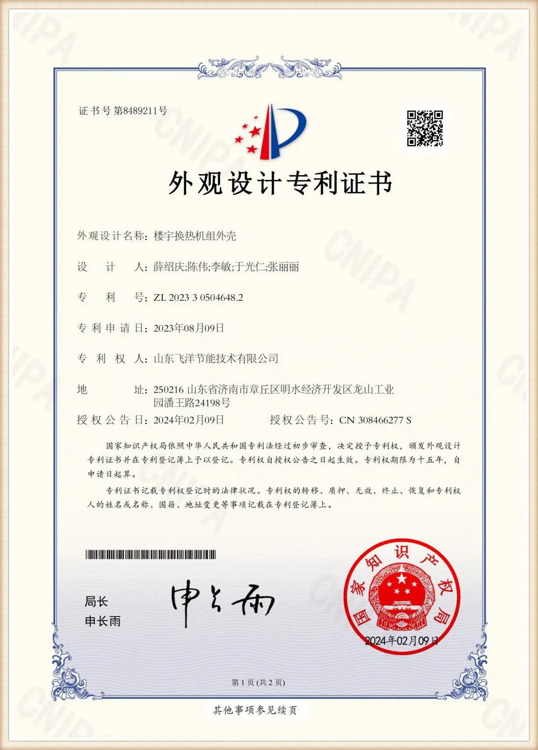

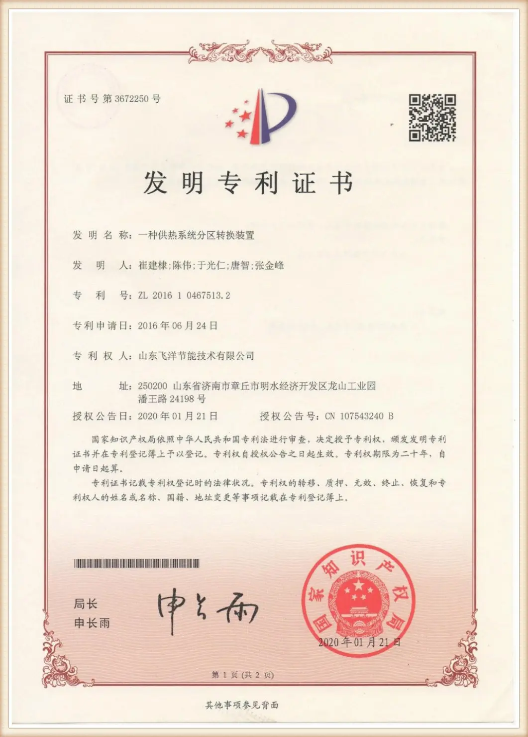
Inside Flotte's 70,000 square meter factory layout.
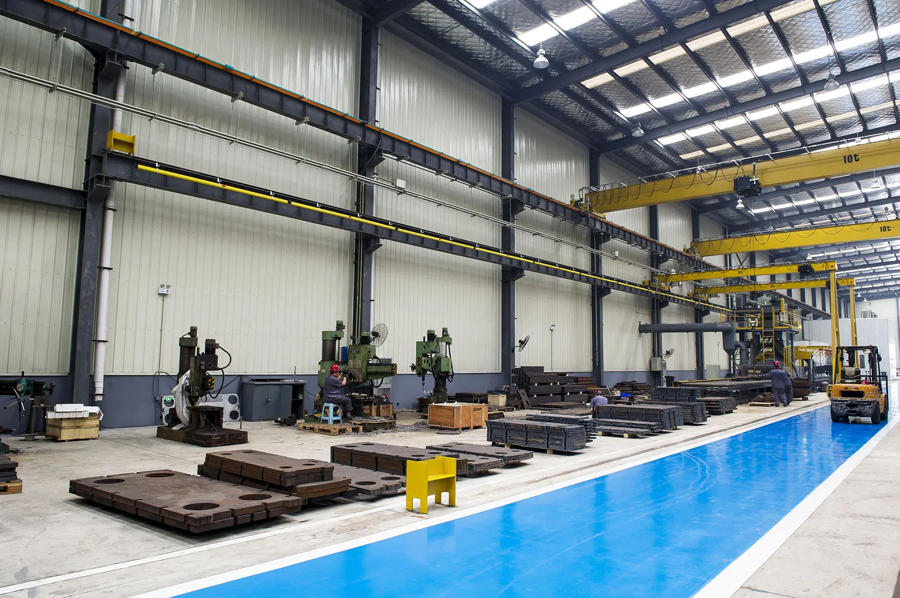

Engineered thermal systems ready for shipment to district heating and industrial sites globally.
 Flotte Energy