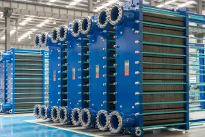
An Engineering Deep-Dive into Hydraulic Resistance, Plate Geometry, and Optimization Methodologies
In modern thermal engineering, the Plate Heat Exchanger (PHE) stands as the pinnacle of compact heat transfer technology. However, the extraordinary thermal efficiency achieved by PHEs is fundamentally linked to fluid dynamics—specifically, the pressure drop ($\Delta P$) experienced by the media as they pass through the channel matrices. Understanding, calculating, and optimizing this pressure drop is not merely a theoretical exercise; it is a critical step for factories, exporters, and EPC (Engineering, Procurement, and Construction) contractors to ensure system reliability, minimize operational pumping costs, and prevent premature equipment degradation.
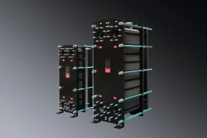
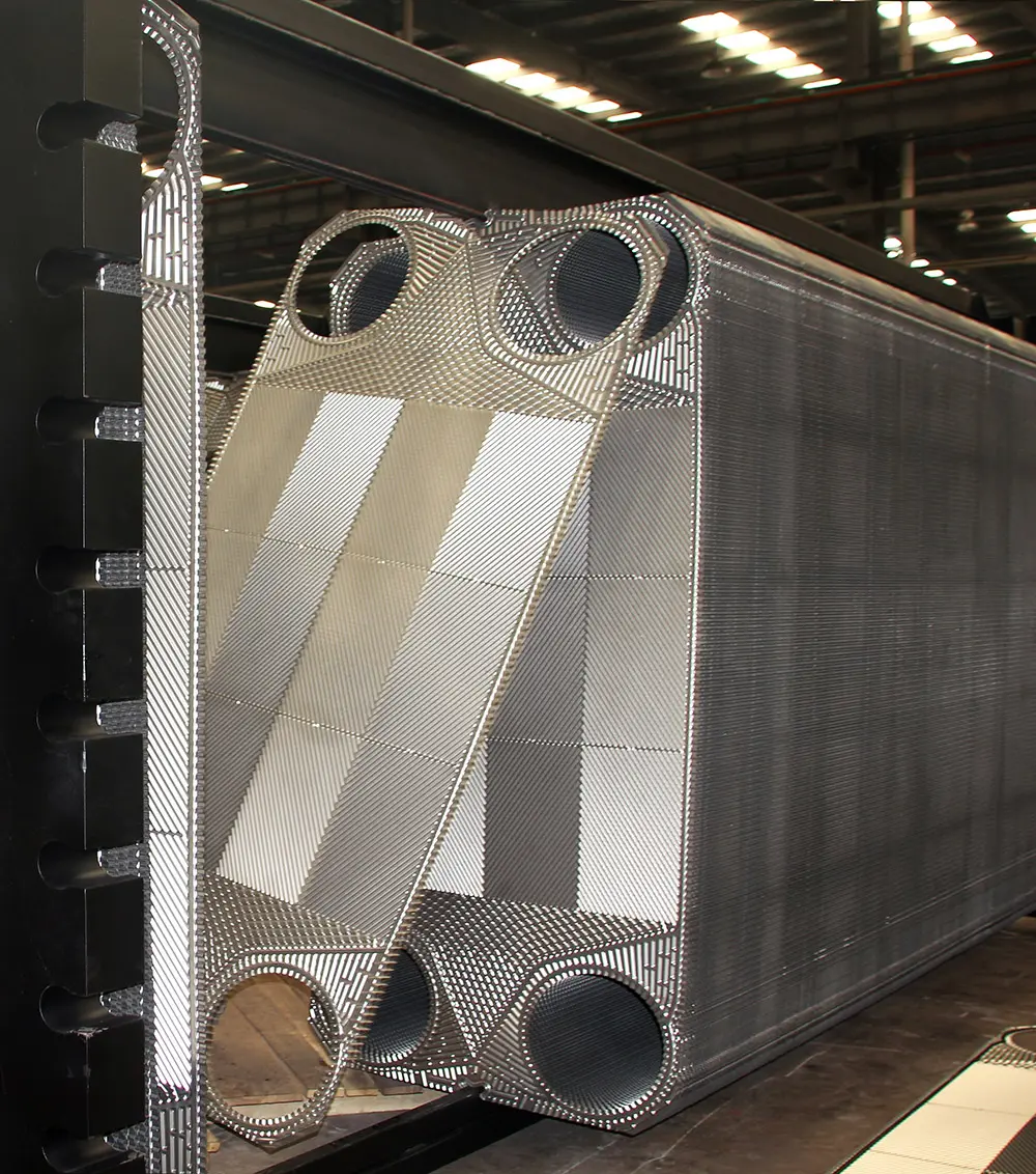
Unlike conventional shell and tube designs, where fluids traverse straight pipes or cross simple baffles, PHEs channel fluids through narrow, tortuous paths formed by corrugated plates. These corrugations, typically pressed in chevron or herringbone patterns, serve a dual purpose: they act as mechanical supports to withstand high pressure, and they induce high turbulence at relatively low Reynolds numbers ($Re < 100$). This turbulence breaks the thermal boundary layer, boosting the heat transfer coefficient, but it simultaneously imposes a significant hydraulic resistance penalty.
The total pressure drop across a plate heat exchanger ($\Delta P_{total}$) is mathematically defined as the sum of two major contributors:
The formula to compute the channel pressure drop is typically modeled as:
Where:
The chevron angle (θ), measured relative to the flow direction, is the primary tool used by design factories to customize PHE performance. Plates are generally categorized into two types:
Advanced manufacturers like Flotte engineer custom mixed-plate configurations, interleaving hard and soft plates to achieve exact thermal requirements without exceeding the client’s allowable pressure drop limits.
Flotte Energy Saving Company: Combining legacy engineering with state-of-the-art production
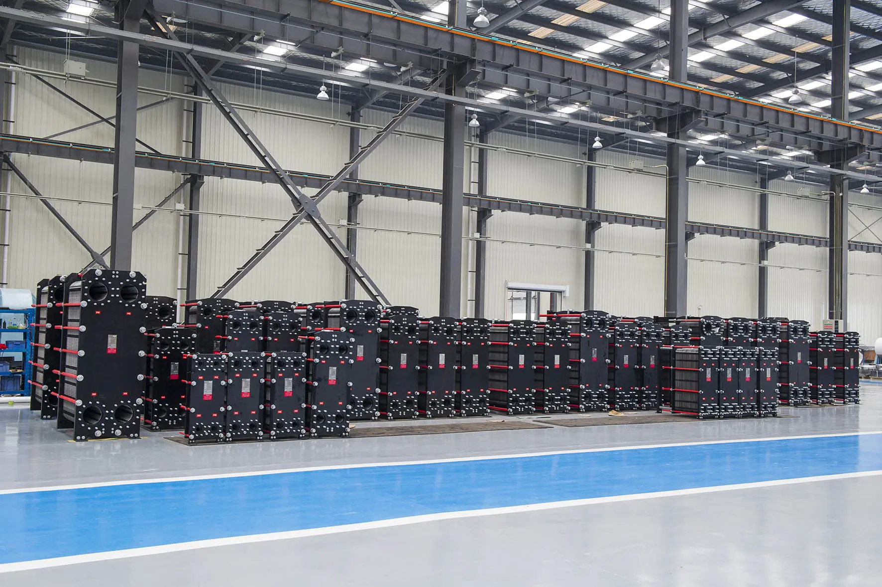
Flotte Energy Saving Company, established in 2013 with a registered capital of 101 million yuan, originated from Flotte Thermal Engineering founded in 1995. With three decades of technical expertise, the company specializes in water equipment, HVAC systems, and water treatment industries. It consistently leads industry peers in adopting cutting-edge technologies, developing innovative products, and delivering comprehensive production and sales services.
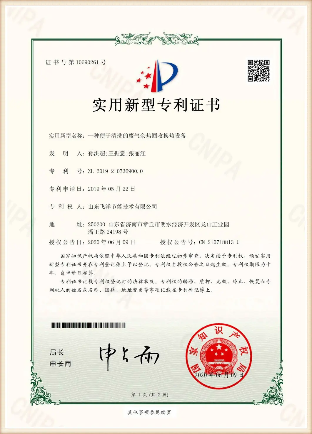
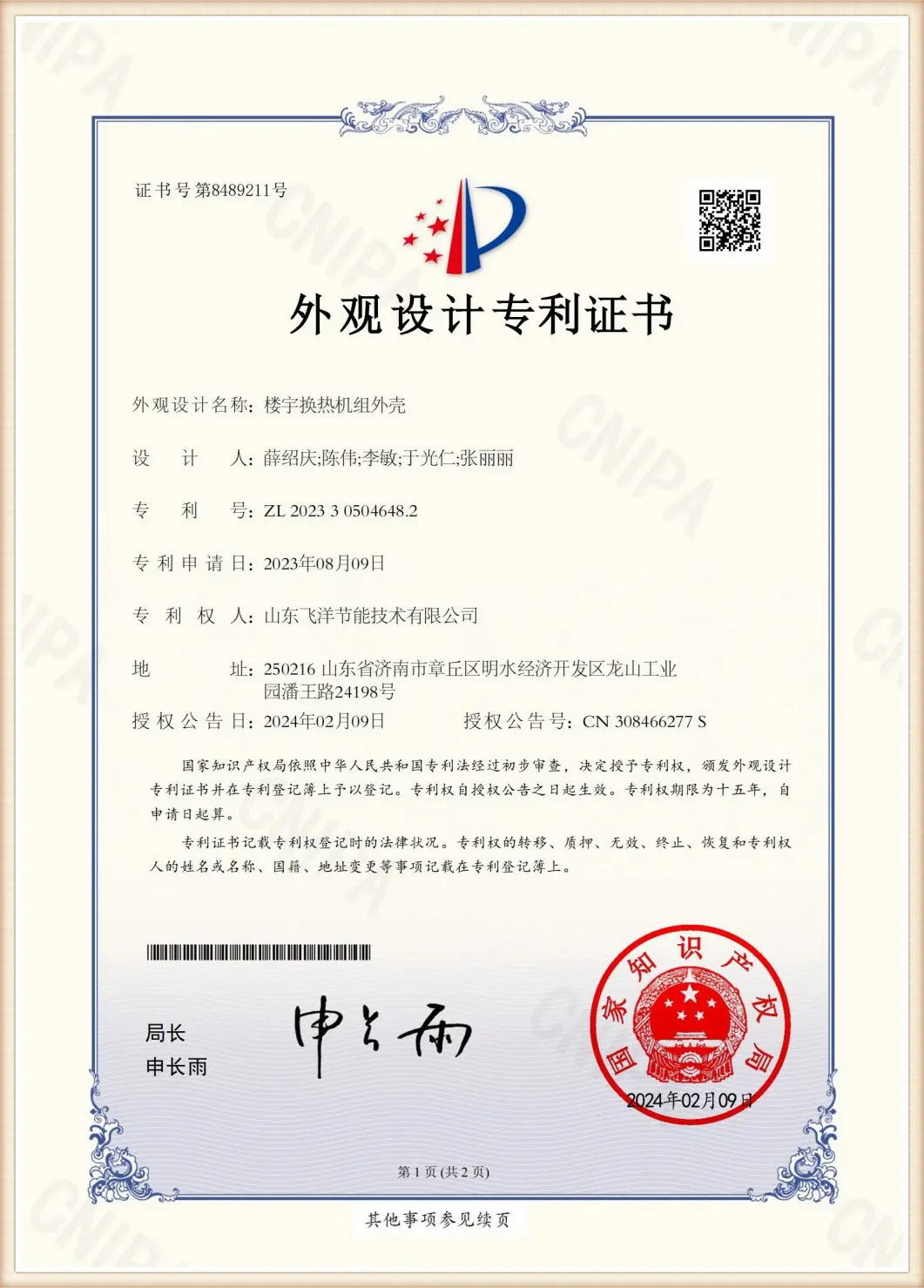
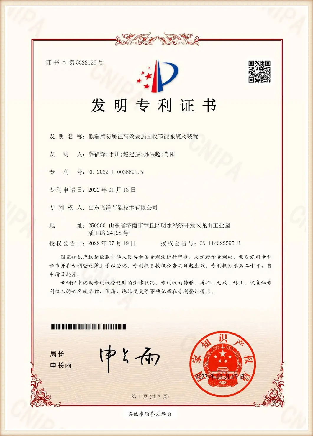
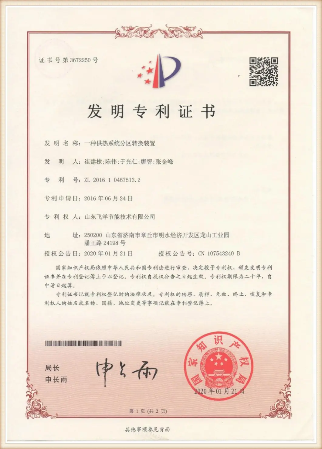
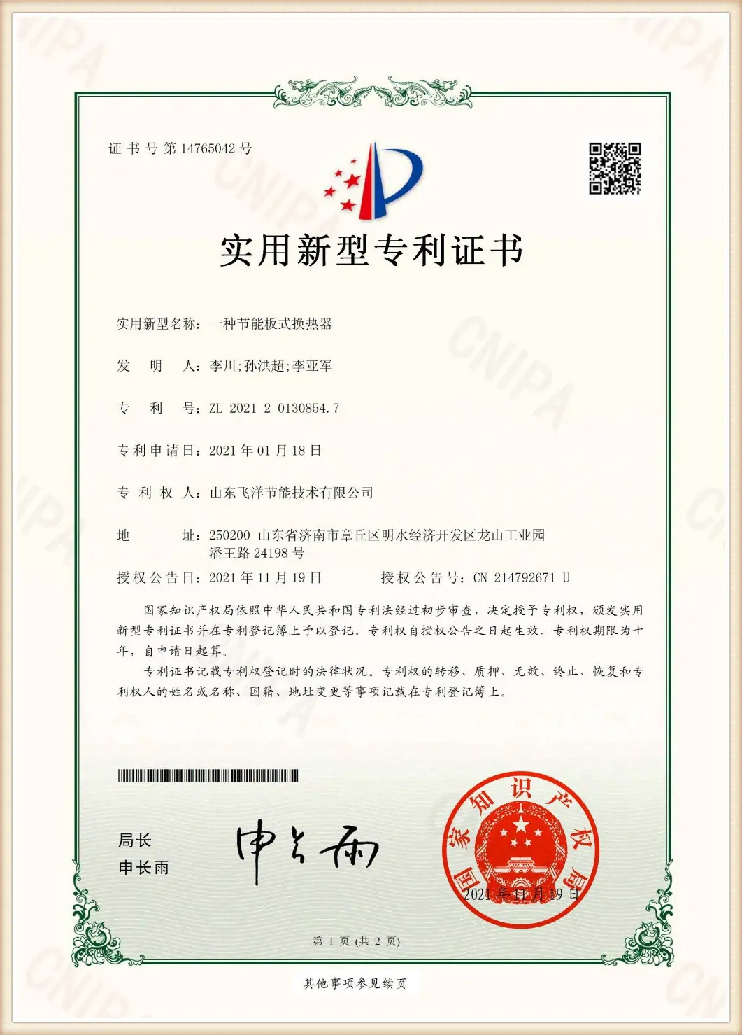
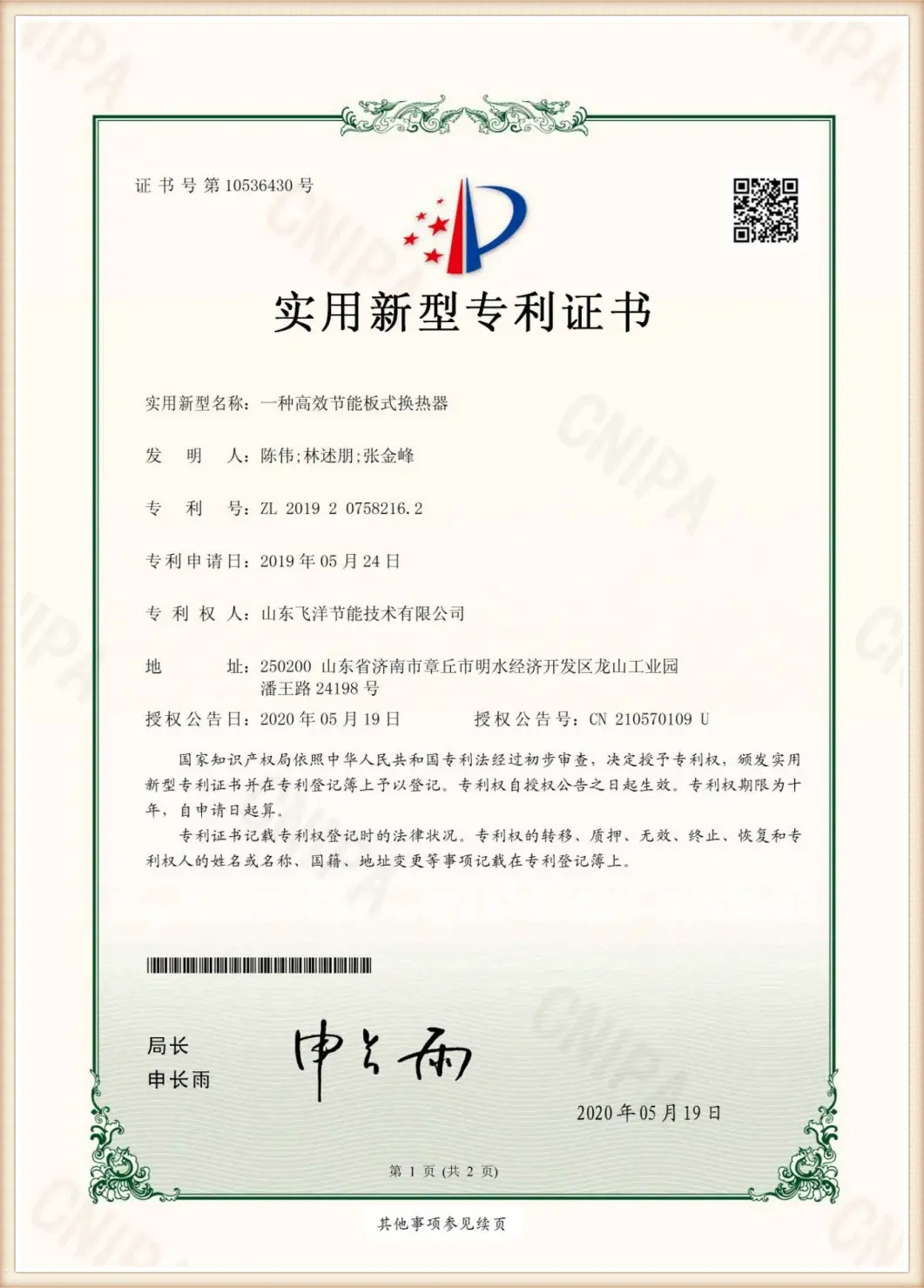
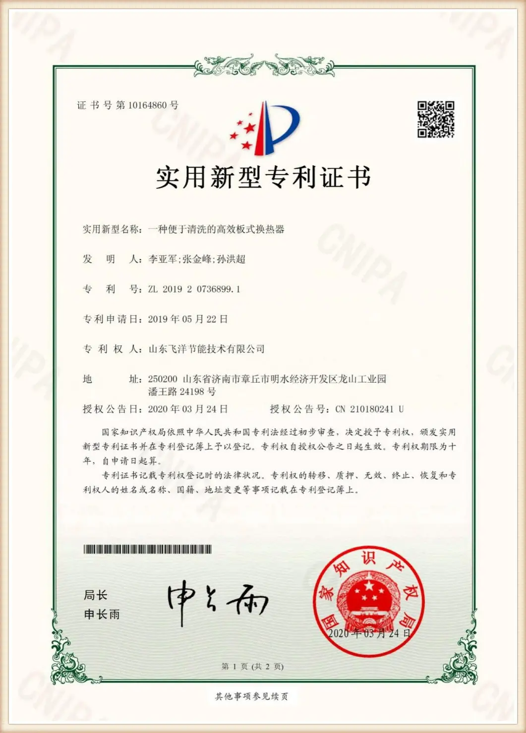
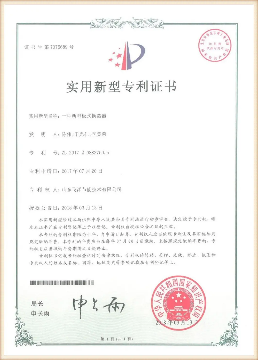
The company has been continuously advancing in production technology innovation, holding multiple patent certifications including "High-Efficiency Plate Heat Exchanger", "Intelligent Plate Heat Exchanger System", and "Plate Heat Exchanger Scale Removal Device". Our products have obtained mandatory national product certification and safety registration from the National Standardization Committee, along with the safety registration for plate heat exchangers issued by the National Boiler and Pressure Vessel Standardization Technical Committee. We have achieved ISO9001 Quality Management System, ISO14001 Environmental Management, and ISO45001 Occupational Health and Safety Management System certifications.
How precise pressure drop calculations dictate global system efficiency
Across diverse industries, plate heat exchangers act as vital thermal gates. However, a pressure drop calculation error can cause system-wide failures. Under-designing leads to inadequate flow, starving thermal processes downstream, while over-designing demands oversized pumps, resulting in high electricity bills and excessive shear stress on gaskets. Below, we look at how various macro-sectors resolve this engineering balance:
In centralized district heating networks, municipal heat sources must deliver warmth to thousands of buildings. Here, detachable plate heat exchangers serve as pressure-isolation barriers between primary and secondary pipe networks. Because primary networks operate over vast distances, maintaining pressure head is critical. Accurate pressure drop calculations prevent primary network pumps from overloading, minimizing thermal distribution losses and ensuring high heat transfer performance.
Chemical processing operates under corrosive conditions, utilizing aggressive fluids like organic solvents, acids, and hydrocarbons. Because these fluids exhibit varying viscosities across operating temperatures, calculations must use dynamic viscosity correction factors. Furthermore, since pumping high-viscosity liquids requires significant energy, minimizing plate resistance is essential. High-theta plates are frequently combined with low-theta plates to keep operational expenses under control.
In the pharmaceutical industry, sanitary requirements are strict. To maintain sterile conditions, flow patterns must avoid stagnant zones where bio-burden can accumulate. Precise calculation of shear stress across the plates helps design channels that encourage self-cleaning velocities, preventing fouling while ensuring that pressure drops remain within pump limits.
| Application Scenario | Typical Fluid Type | Acceptable Pressure Drop Range (kPa) | Primary Calculation Challenge |
|---|---|---|---|
| District Heating (HVAC) | Water-to-Water | 30 - 60 kPa | Optimizing LMTD with low temperature approaches |
| Chemical Processing | Acids, Hydrocarbons | 50 - 100 kPa | Accounting for dynamic viscosity shifts & corrosion allowances |
| Marine Engineering | Seawater to Glycol | 40 - 80 kPa | Managing particulate fouling & seawater density changes |
| Food & Beverage | Dairy, Viscous Juices | 80 - 150 kPa | Preventing product shear degradation and maintaining CIP velocity |
Combining world-class R&D, certified materials, and customized thermal design support
Specializing in plate heat exchangers, it features patented corrugated plate design, achieving 2-3 times higher heat exchange efficiency than conventional equipment. Our in-house calculation engines precisely map thermal performance to flow parameters.
The products cover 8 core areas such as air conditioning, heating and ventilation, and central heating. The solutions have been verified by projects in many places around the world, and can accurately match different regional conditions and compliance requirements.
The whole process quality control system runs through the production, the products have obtained a variety of certifications, and the preferred stainless steel, titanium and other high-end materials ensure stable and durable in harsh environments.
We provide customized design, after-sales maintenance and one-stop service, multilingual team + efficient supply chain, to ensure that global customers can get timely technical and logistical support.
How we ensure calculated parameters match physical performance under real-world conditions
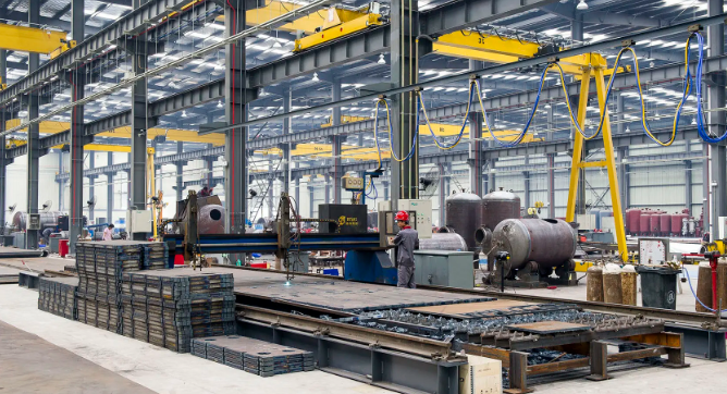
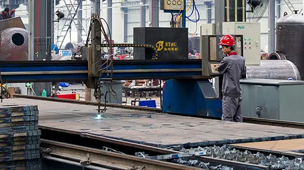
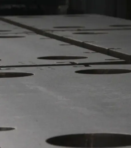
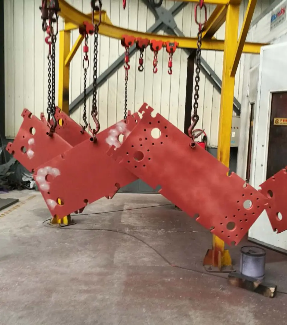
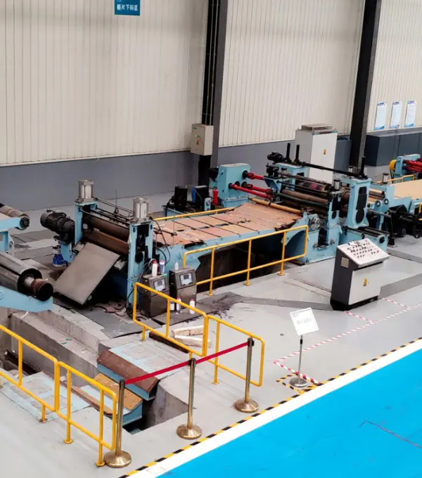
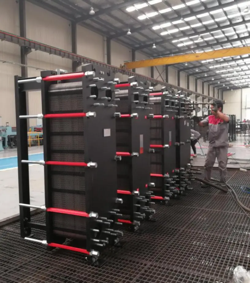
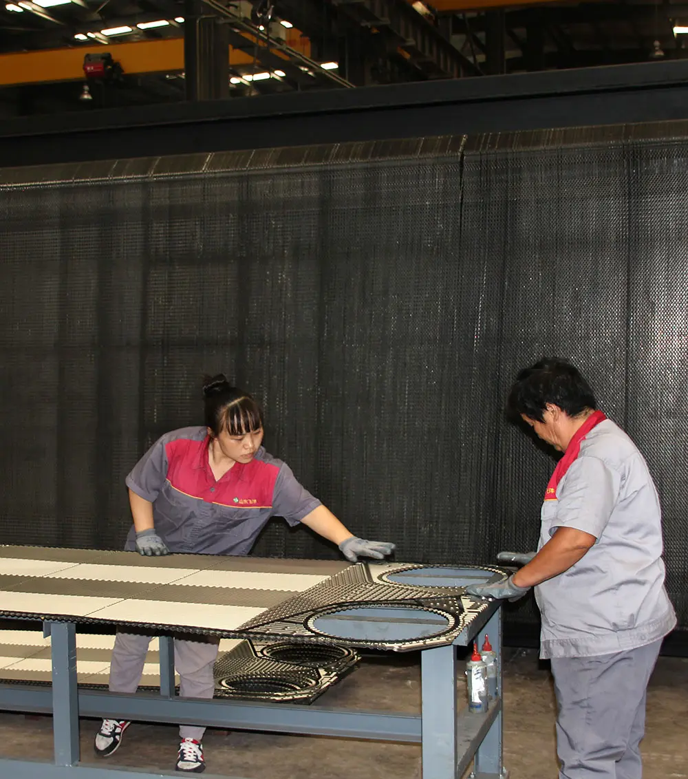
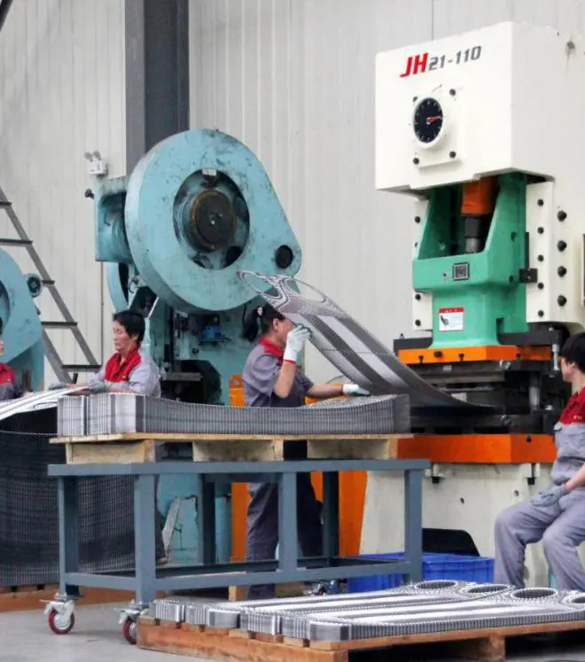
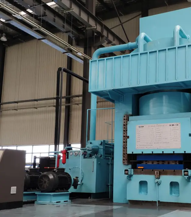
The company operates modern production workshops equipped with advanced manufacturing and quality inspection facilities. All frontline production staff are certified technicians who have undergone rigorous formal training. Production processes, quality control, and service operations strictly adhere to the ISO 9001:2015 international quality management system, while also complying with the pressure vessel quality assurance framework. Our products undergo mandatory inspections by national quality supervision authorities, ensuring full compliance with performance standards.
Adhering to the concept of "quality first" and "winning by quality", the company has established a sound quality assurance system, improved the quality supervision and management of all staff, whole process and all aspects, and made great efforts in product technology, quality and service. The company conscientiously carries out on-site management and rectification work, and establishes a safe and civilized production environment.
Navigating the transition toward AI-driven thermal design and zero-carbon systems
As the international industry shifts toward carbon neutrality, the requirements placed on plate heat exchangers are undergoing a massive evolution. In energy-intensive industries, reducing pressure drop translates directly to power conservation. Moving forward, the roadmap for heat exchanger development focuses heavily on three pillars:
Traditional pressure drop calculations depend on empirical equations that assume uniform flow distribution across all channels. However, real-world conditions often reveal uneven flow distribution, where the central channels receive more fluid than the outer ones. By incorporating AI algorithms trained on massive datasets of operating parameters, designers can now predict local velocity variations. This allows for real-world optimization of plate designs prior to physical production.
In addition to plate shape, surface texture plays a crucial role in flow performance. Micro-grooves and hydrophobic nano-coatings are currently being evaluated to reduce boundary-layer friction. Reducing flow resistance at the boundary wall allows designers to decrease the channel pressure drop by up to 15% without sacrificing heat transfer capacity, representing a significant step forward in efficiency.
Fouling remains a major operational challenge. As scale deposits accumulate inside the plate channels, the effective channel diameter narrows, causing pressure drops to rise. Flotte's patented "Plate Heat Exchanger Scale Removal Device" represents a key mechanical solution to this challenge, enabling continuous, high-efficiency operation without demanding frequent manual cleaning.
Our products comply with international engineering standards and quality codes
Expert answers to critical pressure drop and thermal engineering questions
 Flotte Energy