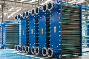
Established in 2013 with a registered capital of 101 million yuan, Flotte Energy Saving Company originated from Flotte Thermal Engineering founded in 1995. With three decades of rigorous technical expertise, the company specializes in water equipment, HVAC systems, and water treatment industries. It consistently leads industry peers in adopting cutting-edge technologies, developing innovative products, and delivering comprehensive production and sales services.
Our specialized engineers translate complex thermodynamic requirements into highly optimized hydraulic oil cooler diagrams, delivering peak operational reliability and maximizing system uptime. By leveraging modern fluid dynamics, we design tailored systems that serve heavy manufacturing, power generation, chemical processing, and municipal central heating networks worldwide.
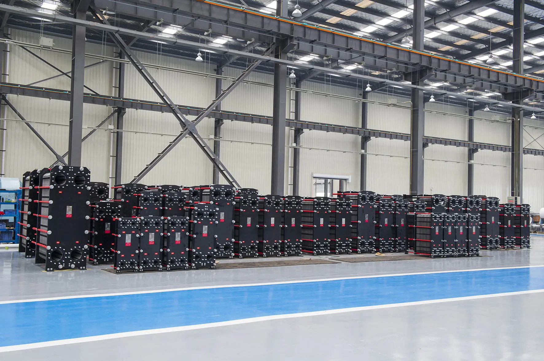
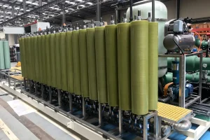
Examine our highly engineered industrial heat exchangers, membrane concentration systems, and intelligent district heating solutions built for complex modern hydraulic machinery.
In modern heavy-duty industrial machinery, marine engineering, and power plants, thermal management is not merely a utility—it is a critical determinant of system longevity and operational efficiency. The hydraulic circuit functions as the lifeblood of large-scale mechanical systems. Consequently, excessive thermal load in hydraulic fluid changes its viscosity, degrades synthetic and natural seals, speeds up oil oxidation, and triggers cavitation in hydraulic pumps. To circumvent these failures, design engineers and procurement officers heavily rely on a detailed hydraulic oil cooler diagram.
For international procurement professionals, a hydraulic oil cooler diagram represents more than just drawing symbols. It details structural parameters, bypass valve locations, cooling medium path integrations, and design compliance profiles. Standard components included in our specialized blueprints are:
Each industrial sector exhibits distinct challenges regarding thermal management. A standard "one-size-fits-all" cooling unit often fails when exposed to extreme marine humidity, acidic process chemicals, or sub-zero northern central heating conditions. Below is a analysis of our targeted industry configurations:
High temperature and abrasive dust environments demand highly resilient oil coolers. Our designs feature reinforced brazed joints and built-in mechanical clean-outs to maintain high thermodynamic output despite dust contamination.
Marine systems suffer from saline corrosion. Flotte uses premium Titanium plate structures and Copper-Nickel alloy tube networks in our heat exchangers, protecting them against seawater corrosion.
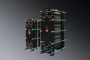
District heating systems use plate heat exchangers to transfer energy from primary municipal loops to local building stations. This manages pressure differentials and ensures consistent heating across dense metropolitan developments.
In centralized municipal heating projects, plate heat exchangers play an essential role. They transfer heat from primary networks to local loops, helping regulate supply water temperatures, limit pipeline pressure losses, and ensure residents remain warm and comfortable throughout winter.
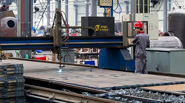
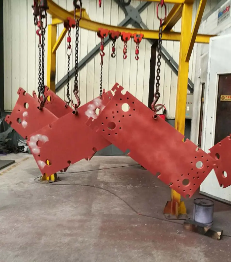
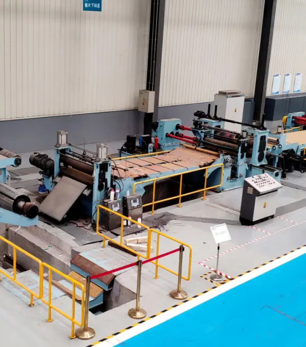
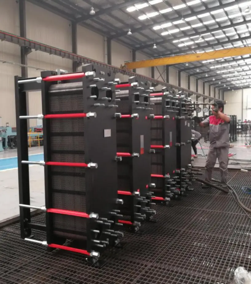
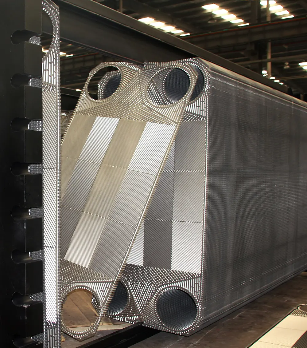
We implement a strict step-by-step manufacturing cycle under ISO 9001:2015 conditions. Check our certified thermal equipment production phases below.
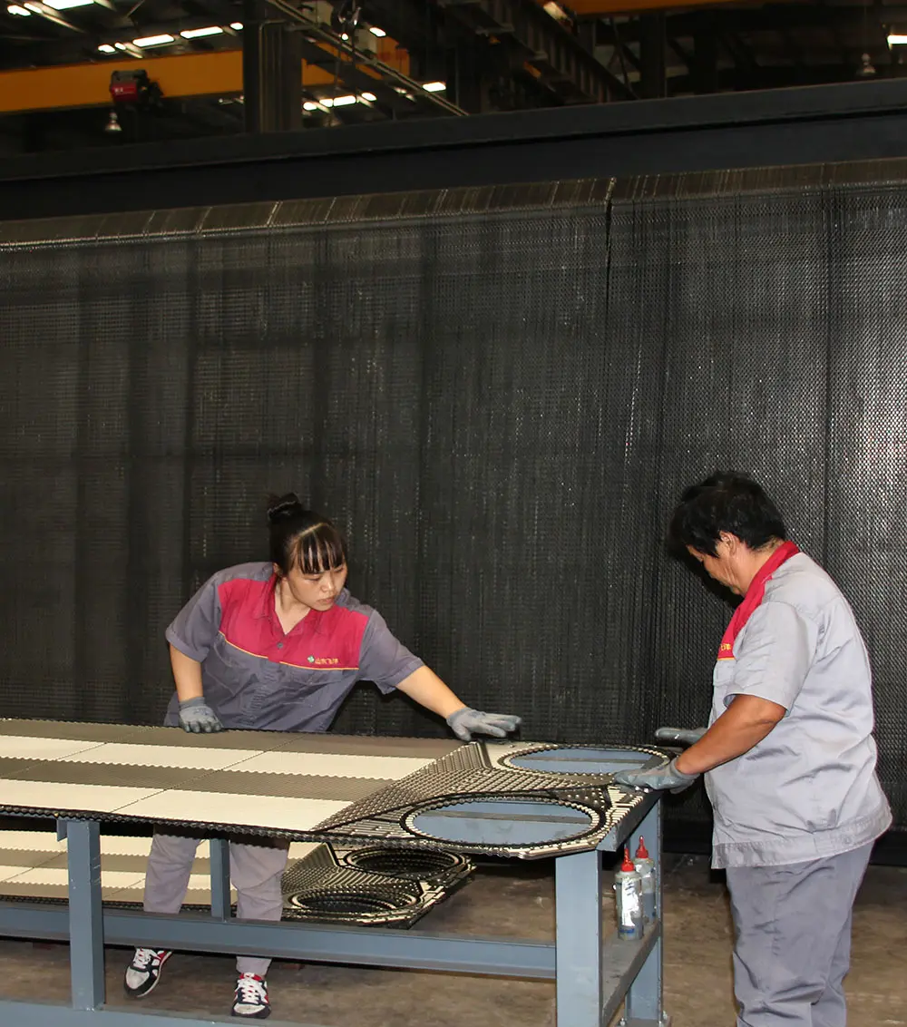
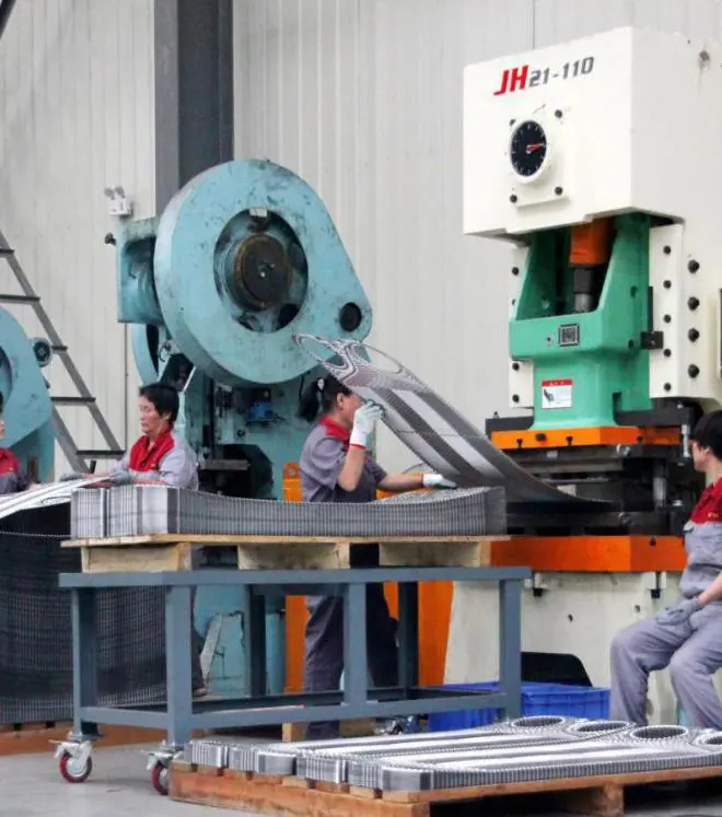
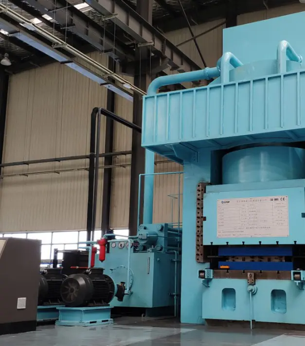
The fluid dynamics sector is undergoing transition driven by digitalization and sustainable environmental regulations. In response, Flotte is actively implementing next-generation designs in our production lines.
Key innovations on our design roadmap include:
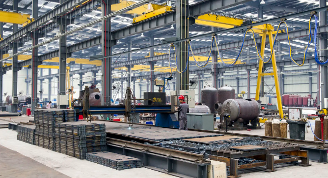
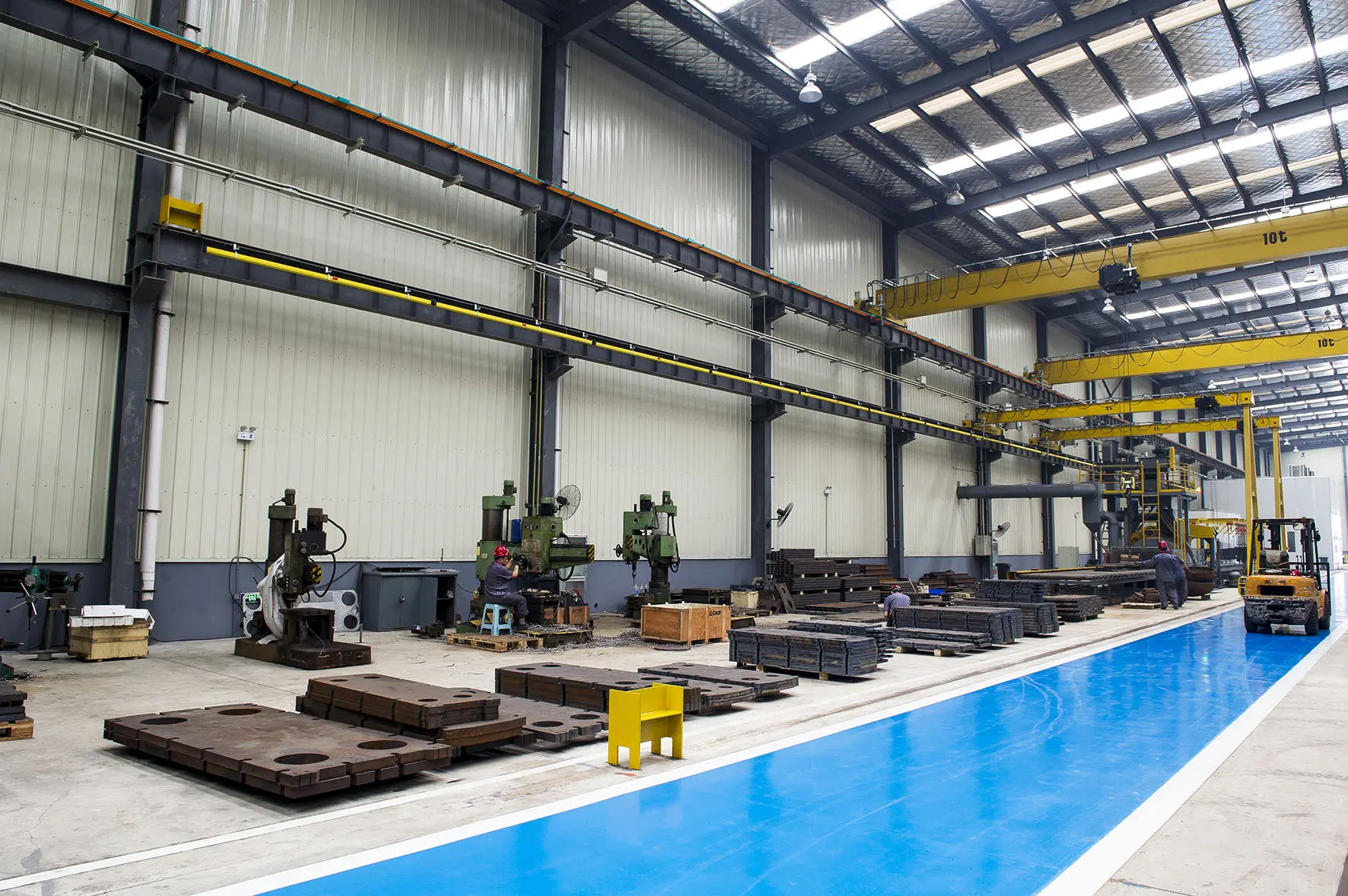
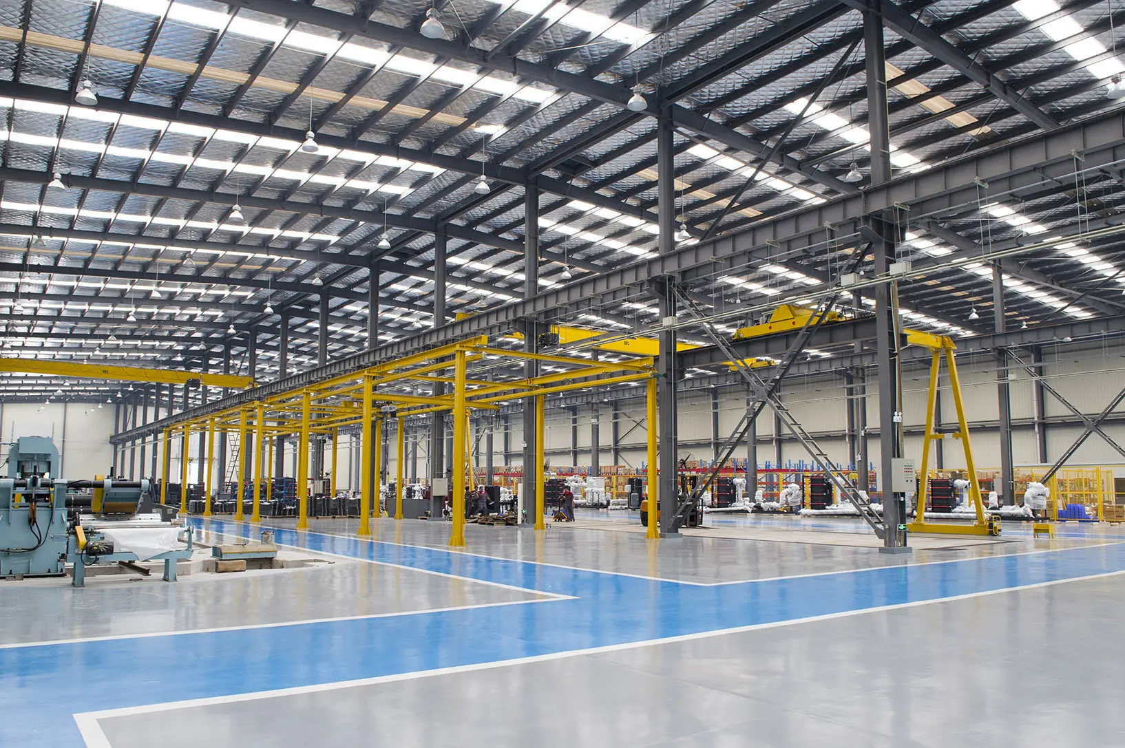
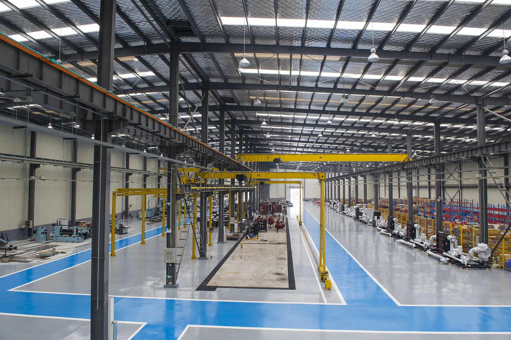
Our ISO 9001:2015-certified facility runs modern plate stamping machines and automatic testing tables. Frontline workers undergo continuous technical training, ensuring every joint, gasket, and weld meets high quality standards. All pressure vessels pass hydrostatic and helium leak tests before leaving the factory. This rigorous process guarantees they can withstand continuous pressure fluctuations in challenging field environments.
Browse through our major engineered components, featuring automated systems, multi-effect evaporators, HVAC units, and heavy-duty industrial valves.
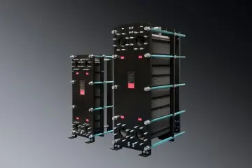
Engineered for straightforward mechanical maintenance, optimized for heavy hydraulic oil circulation systems.
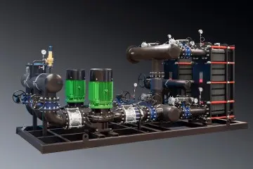
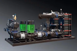
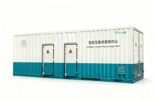
Pre-piped, skidded package featuring automated smart valves, integrated control system, and energy-saving functions.
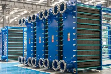
Built for municipal district energy grids demanding high thermal safety margins and pressure stability.
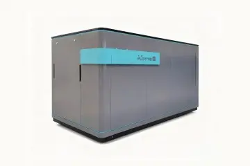
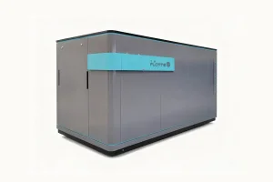
Commercial building HVAC heating energy separation unit, engineered to fit compact basements and mechanical rooms.
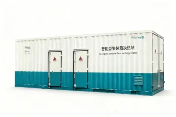
All-weather exterior enclosure protects sensitive valves, instrumentation, and control interfaces from dust and rain.
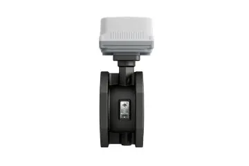
Precise hydronic balancing valve for district pipelines, preventing thermal drift across complex multi-branch loops.

IoT sensor node that relays local temperature readings to coordinate main HVAC pump speed.
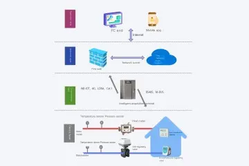
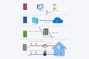
Software and hardware integration platform for real-time monitoring and thermal output optimization.
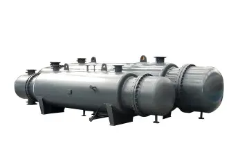
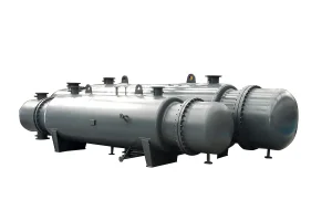
Time-tested heavy industrial architecture, ideal for highly viscous oils and extreme pressure conditions.
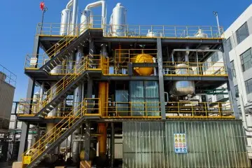
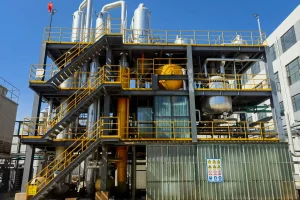
Advanced steam utilization system designed for chemical concentration and industrial wastewater treatment.
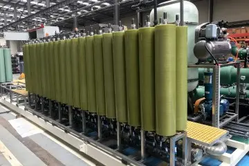
High-efficiency, cost-effective system designed for liquid desalination, chemical purification, and separation processes.
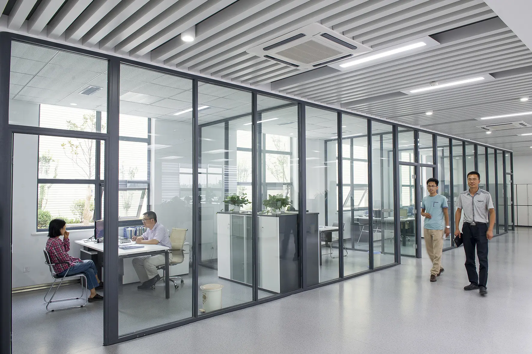
A look inside our manufacturing floor, stamping departments, testing laboratories, and official quality certifications.
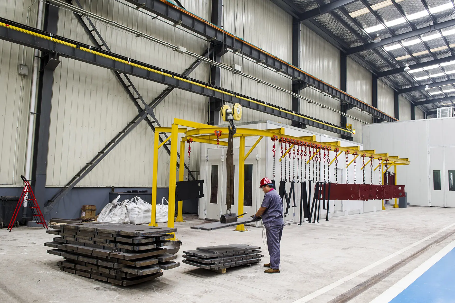
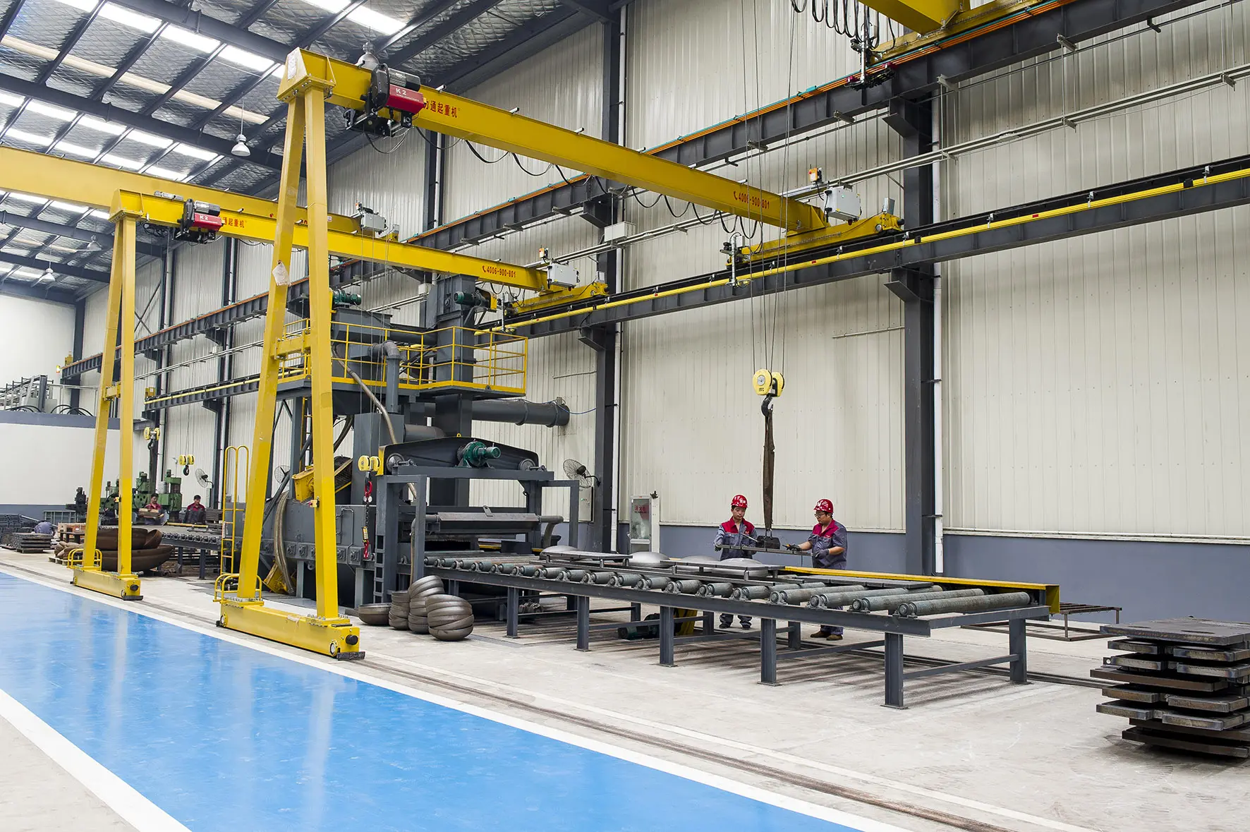


ISO 9001 Certification
ISO 14001 Certification
ISO 45001 Certification
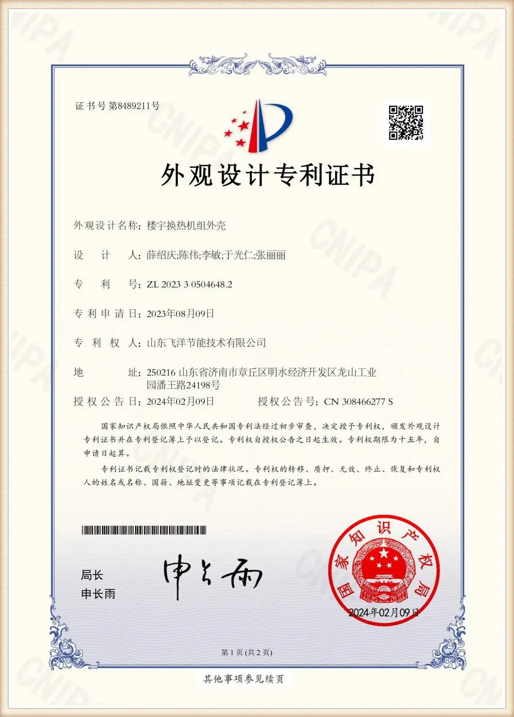
Safety Design Patent
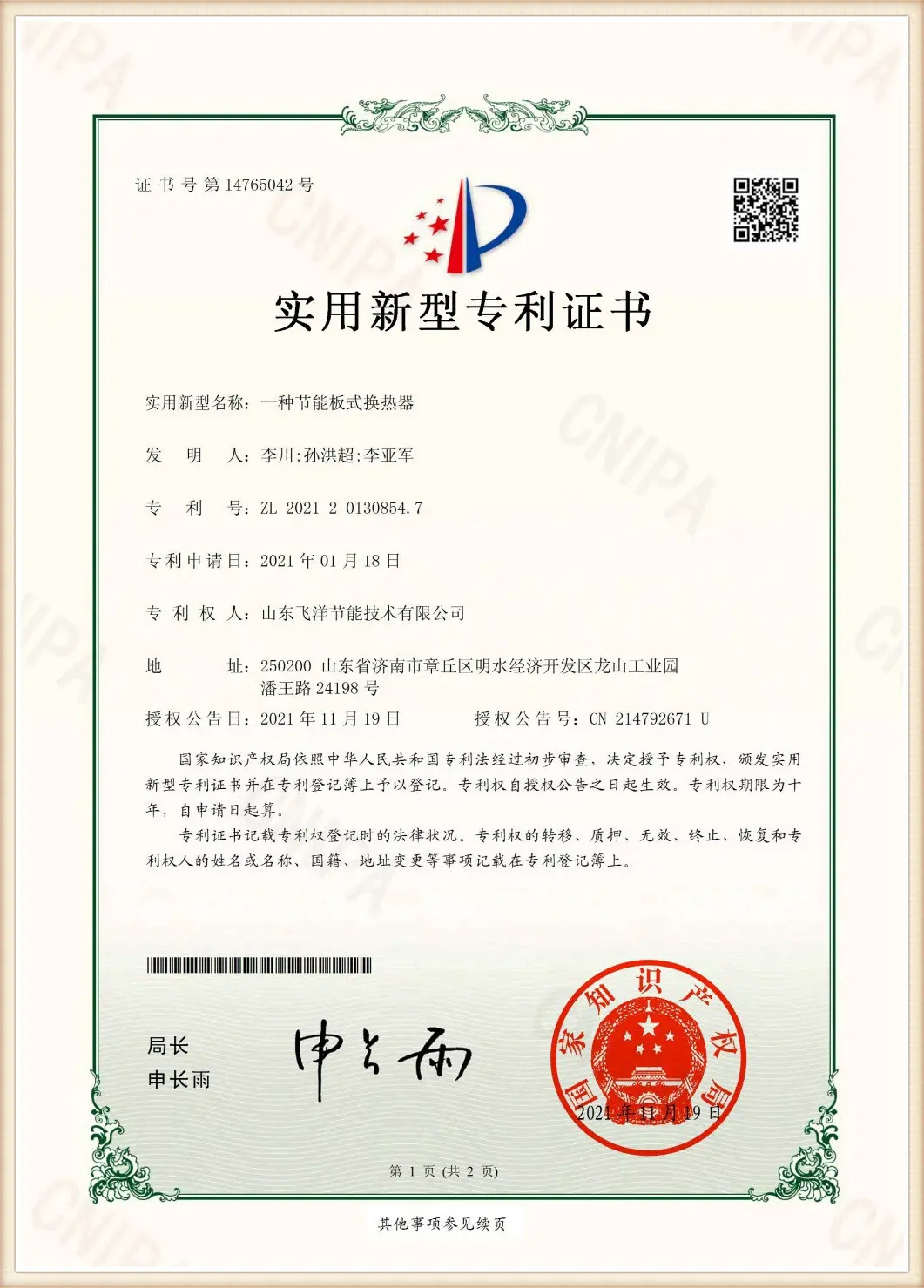
CCC System Approval
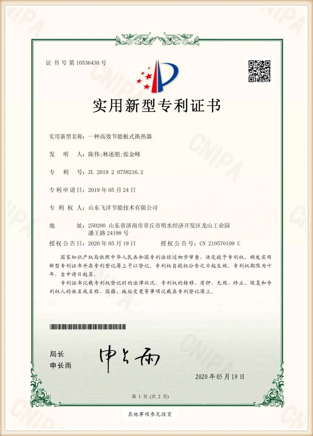
Pressure Vessel License
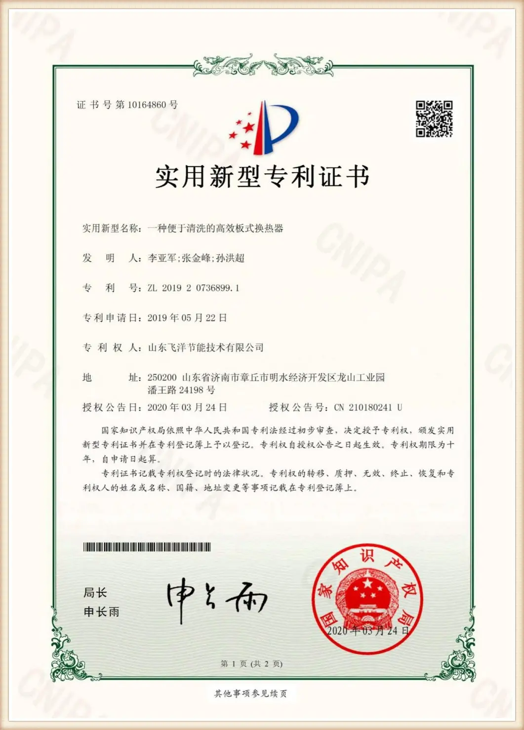
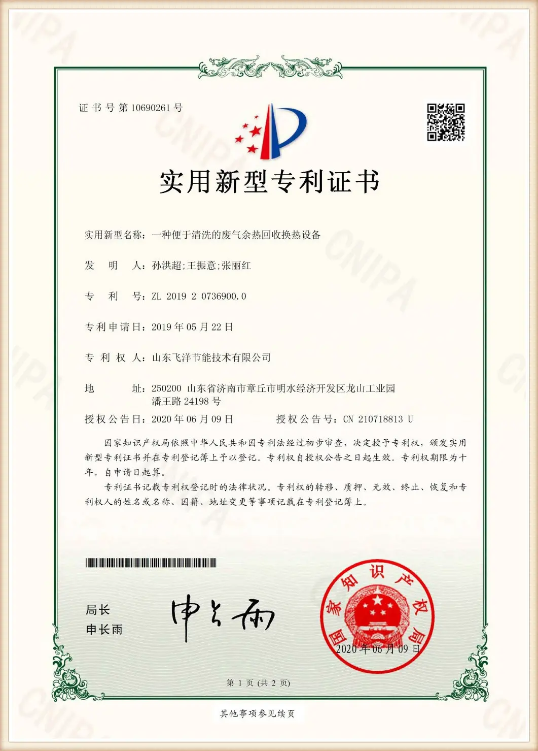
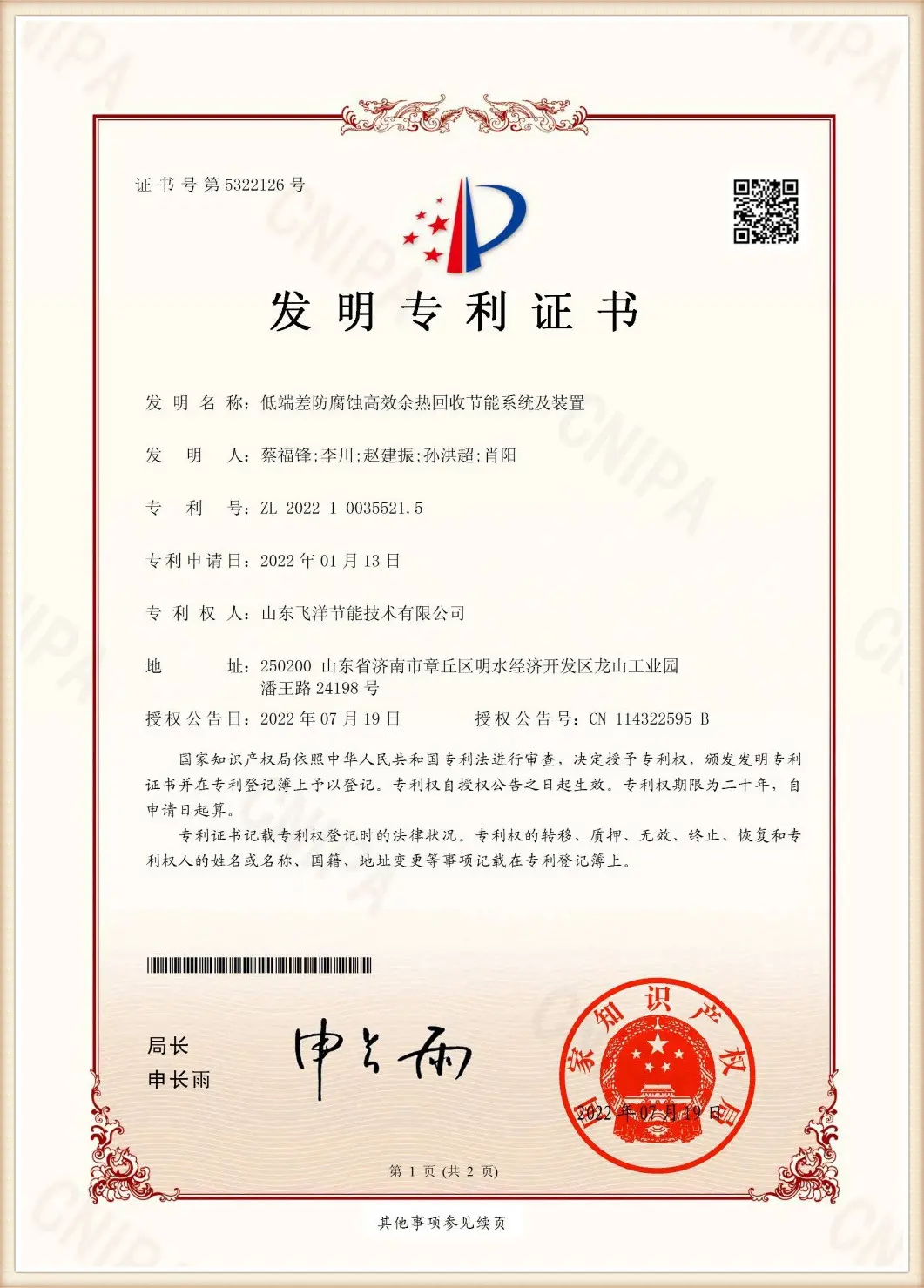
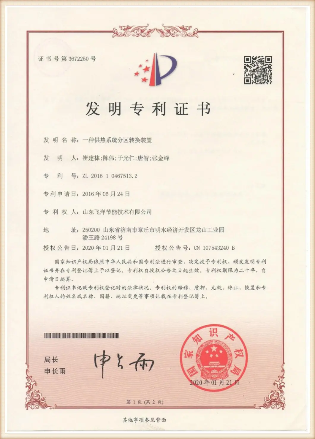
Utility Patent Award
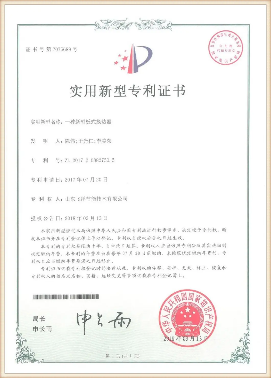
Thermal Tech Certificate
For exporters and global distributors, manufacturing the cooling unit is only half the battle. Delivering it safely, matching regional electrical codes, and providing localized technical documentation is what ensures a smooth installation process.
Flotte offers comprehensive localization and compliance features:
Get expert answers to common questions about hydraulic oil cooler schematic symbols, performance calculations, and system selection.
On standard ISO 1219/DIN 24300 hydraulic schematics, a oil cooler is represented by a diamond-shaped symbol with two internal lines depicting fluid paths, accompanied by cold-source arrowheads pointing outward. Advanced diagrams from Flotte also display the thermal bypass loop, represented by a spring-loaded non-return check valve, and a digital sensor port shown as an encircled 'T' inside the main fluid pipe.
Proper sizing depends on the system's heat dissipation requirement ($P_{diss}$), which is estimated as a percentage of the total input power (often 20% to 30% for standard hydraulic systems, and up to 50% for high-pressure systems like hydrostatic drives). The formula used is:
P_diss = Q * C_p * p * dT
Where Q is the volumetric flow rate, C_p is the specific heat capacity of the hydraulic fluid, p is the fluid density, and dT is the target temperature drop. After defining these values, our engineers select a plate arrangement that provides sufficient surface area while keeping the oil's pressure drop below 0.05 MPa to prevent line restrictions.
When a hydraulic system starts in low-temperature environments, the oil is highly viscous. If this cold, thick oil is pushed directly into the narrow channels of the cooler, it generates high back-pressure that can damage the heat exchanger plates or rupture seals. A thermostatic bypass valve routes the oil around the cooling core until the fluid reaches its optimal operating temperature (typically 45°C), protecting the system and reducing startup wear.
Fouling occurs when suspended particulates, scale deposits, or oxidized oil residues build up on the heat transfer plates, creating a thermal barrier that reduces efficiency. Flotte prevents this by using a high-turbulence chevron plate design that creates self-cleaning flow currents. We also use premium gasketed designs that allow the plate pack to be easily opened, cleaned, and re-bolted during scheduled maintenance.
Yes. Traditional NBR rubber gaskets can degrade when exposed to synthetic esters or biodegradable oils. Flotte solves this by offering custom gasket options made from Viton (FKM) or peroxide-cured EPDM, ensuring chemical compatibility, zero leakage, and a long service life with eco-friendly hydraulic fluids.
Examine our highly engineered industrial heat exchangers, membrane concentration systems, and intelligent district heating solutions built for complex modern hydraulic machinery.
 Flotte Energy