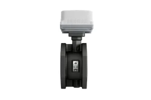
Deploying patented chevron geometries and intelligent system controls designed to maximize the thermal transfer limits configured during the sizing phase.
Flotte Energy Saving Company, originally founded as Flotte Thermal Engineering in 1995 and formalised with a registered capital of 101 million yuan in 2013, represents three decades of elite-level engineering execution. As a prominent designer, manufacturing factory, and exporter, Flotte specializes in heat recovery systems, district HVAC networks, industrial water treatment, and specialized thermal management configurations. By pairing theoretical precision with high-capacity production, we provide mechanical systems designed to last under challenging plant operations.
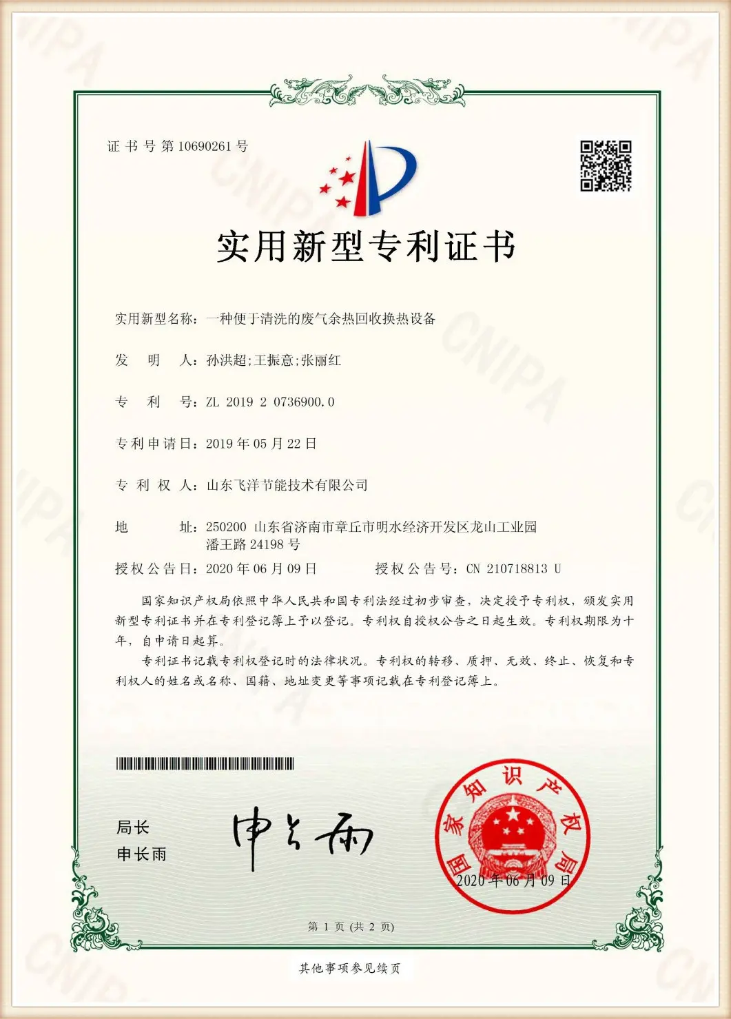
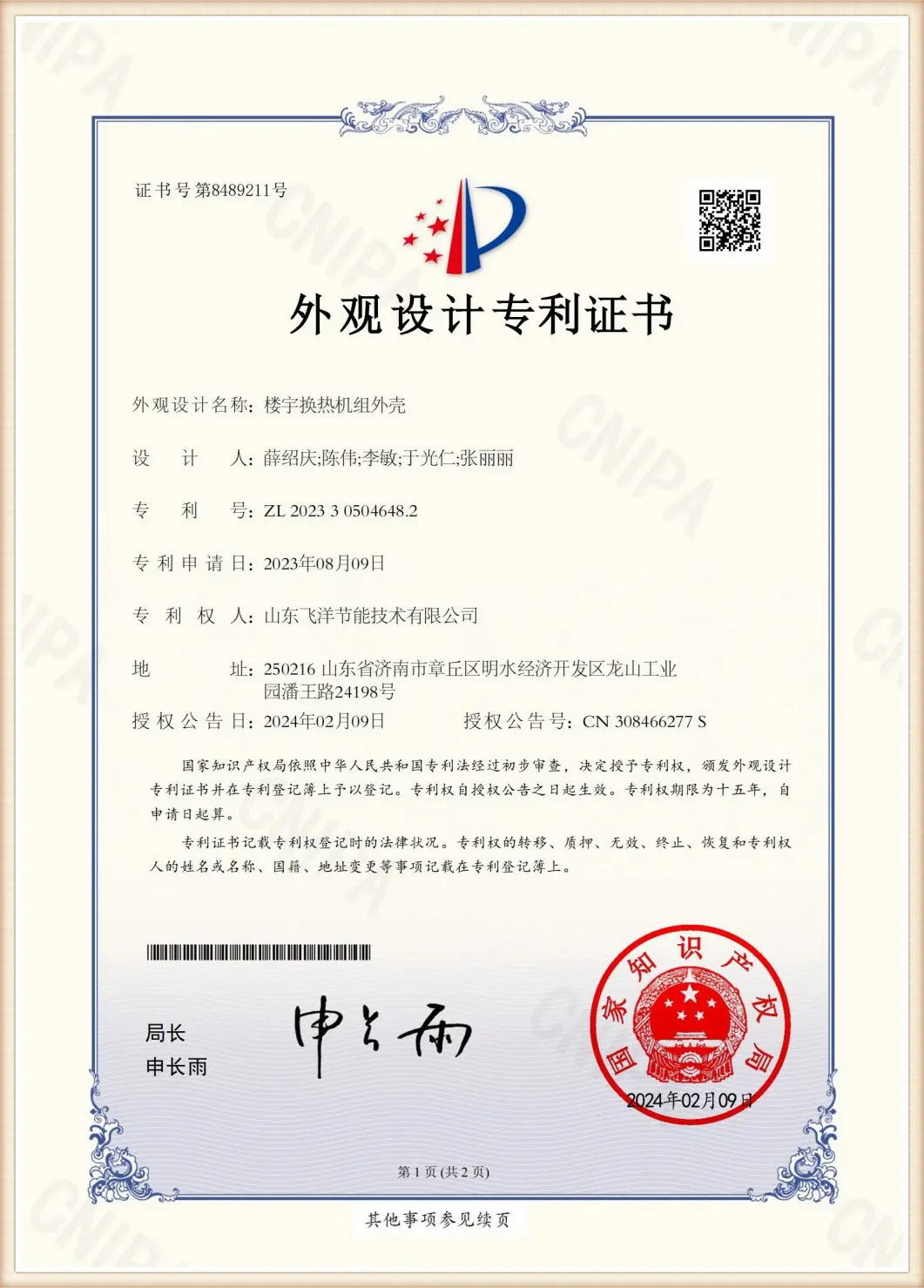
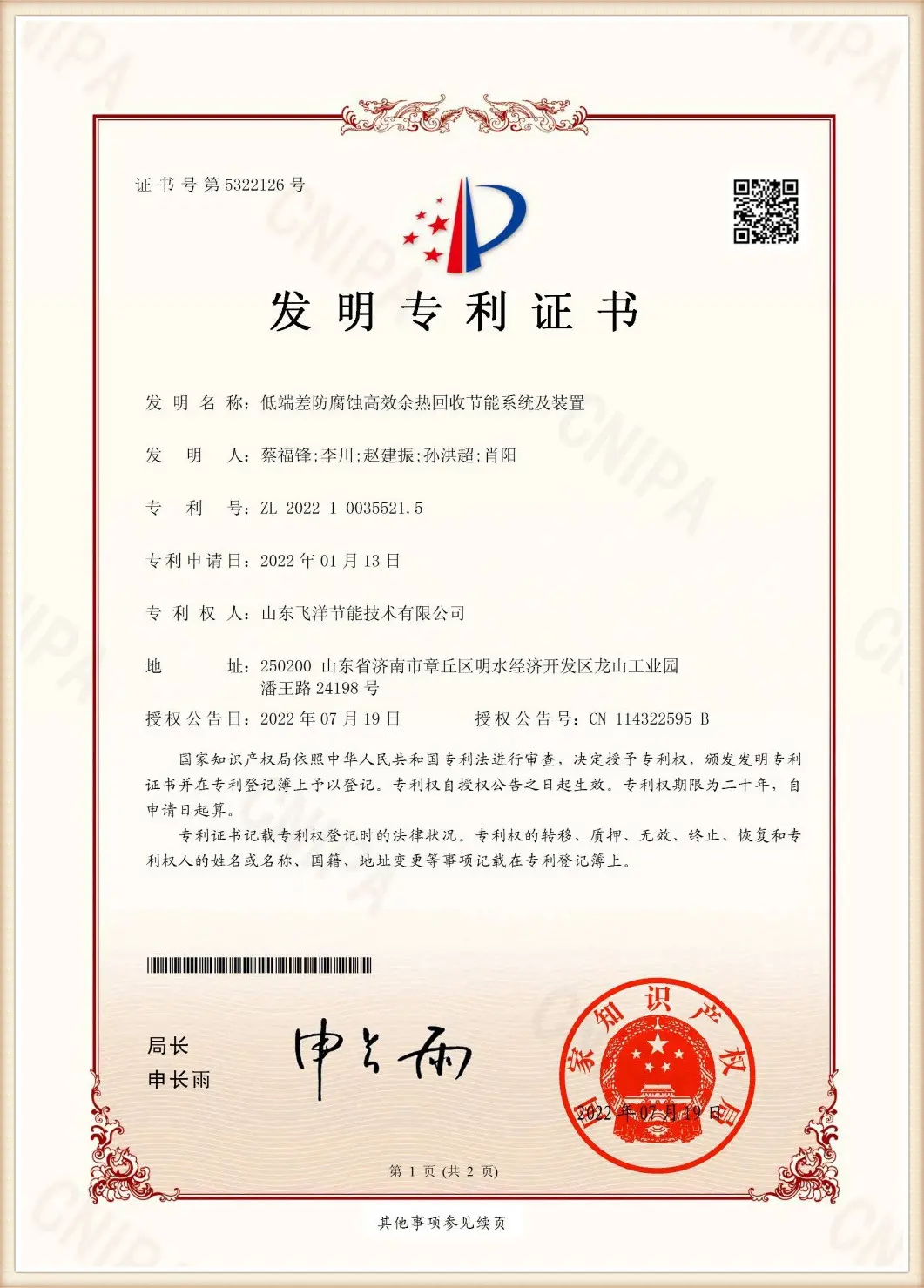
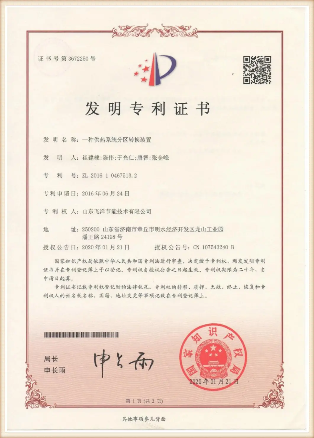
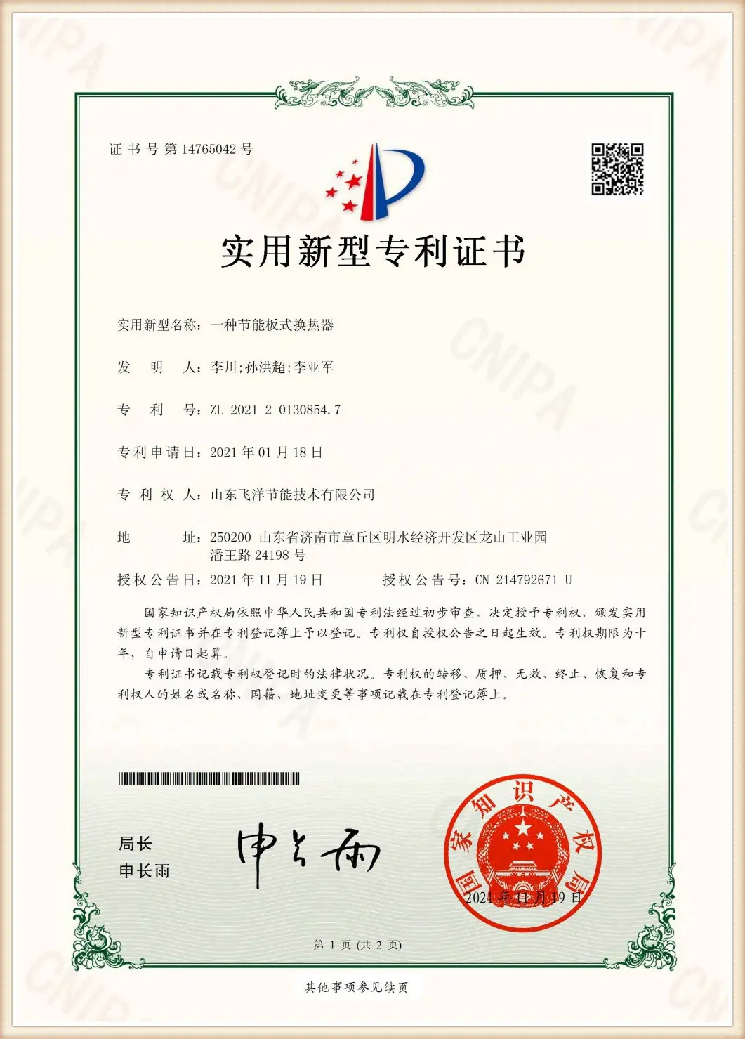
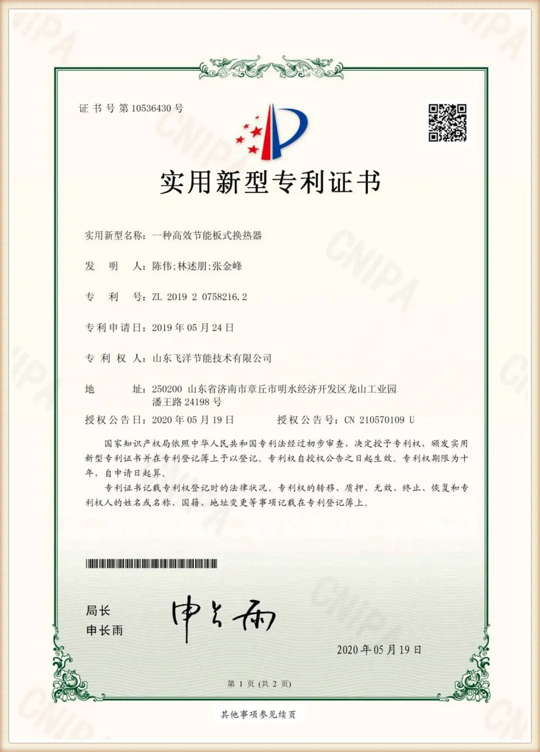
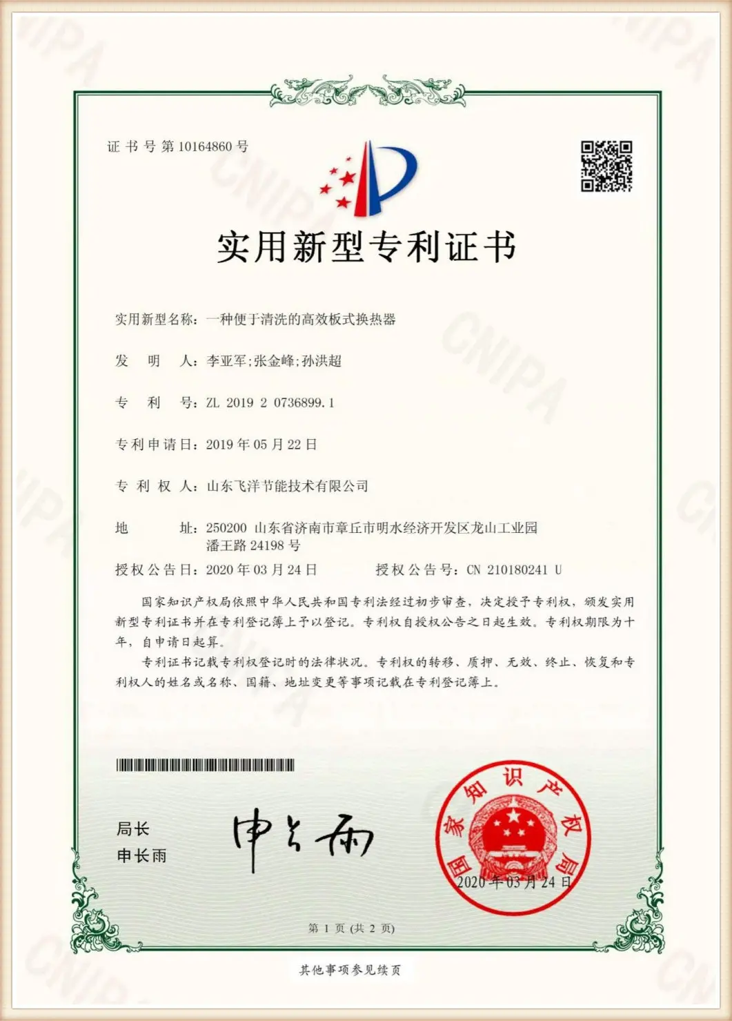
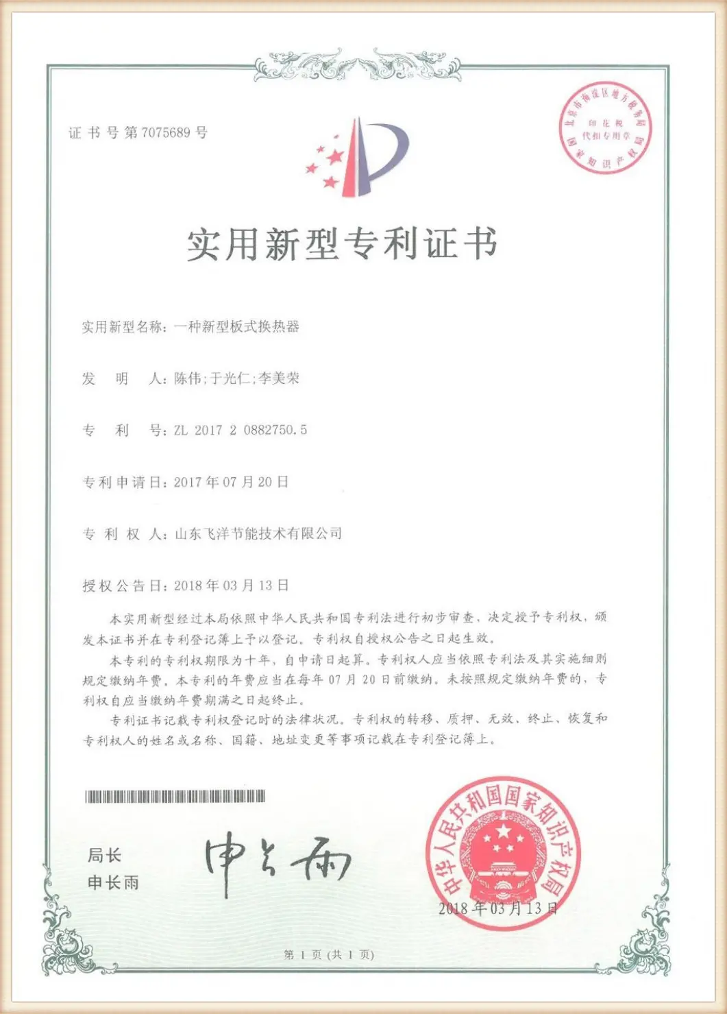
Our core manufacturing processes comply fully with local and global regulatory standards, validated by certifications including the ISO 9001:2015 International Quality Management System, ISO 14001 Environmental Management System, and ISO 45001 Occupational Health and Safety System. Furthermore, we maintain specialized manufacturing licenses for pressure vessel fabrications, safety registrations from the National Boiler and Pressure Vessel Standardization Technical Committee, and multiple utility patents including "High-Efficiency Plate Heat Exchangers" and "Plate Heat Exchanger Scale Removal Devices".
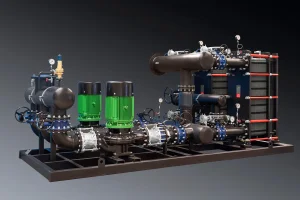
In modern process plants, central district heating networks, and HVAC projects, global procurement teams are shifting away from nominal sizing lists. They require deep verification of PHE Heat Exchanger Calculation parameters to ensure maximum operational uptime, minimized footprint, and long-term energy savings. The procurement of Plate Heat Exchangers (PHE) is no longer a commodity transaction; it has become an integrated thermodynamic optimization process.
Procuring entities in Europe, North America, and Southeast Asia demand adherence to ASME Section VIII, PED 2014/68/EU, and local structural wind/seismic configurations. Sizing calculations must balance these physical constraints.
Calculations determine not just initial costs but operating expenditures (OPEX). Minimizing pressure drop limits pumps' electrical load requirements, directly cutting overhead expenses across the plant's lifetime.
Aggressive chemistry requires exact plate calculations. By analyzing thermal resistance, boundary layers, and corrosion rates, engineers select the correct material thicknesses (0.5mm to 0.7mm) and alloys (316L, Titanium, Hastelloy).
Proper PHE configuration avoids the dual hazards of over-sizing (excessive capital expenditure and low flow velocities causing rapid bio-fouling) and under-sizing (failure to meet target cooling/heating profiles and massive system pressure drops). Sizing calculations utilize two core methods: the Logarithmic Mean Temperature Difference (LMTD) method and the Number of Transfer Units (NTU) approach.
Before executing dimensional calculations, the total heat load ($Q$) must balance between the hot and cold fluid circuits:
Where $m$ is the mass flow rate, $C_p$ is the specific heat capacity at mean fluid temperature, and $T$ represents the inlet and outlet temperatures of the hot ($h$) and cold ($c$) process streams.
For true counter-current configurations, LMTD represents the effective thermal driving force across the plate pack length:
When multi-pass routing or asymmetric thermal profiles occur, a correction factor ($F$) is calculated such that the effective temperature difference becomes: ΔTeff = F • ΔTlm.
The total heat transfer coefficient ($U$) accounts for the convective heat transfer resistances on both fluid boundary layers, the conductive resistance of the alloy sheet, and the fouling resistances ($R_f$):
Here, $h_h$ and $h_c$ represent the film coefficients calculated from the Nusselt Number ($Nu$), which depends heavily on plate corrugation patterns, channel velocities, and Reynolds Numbers ($Re$). $\delta$ is the plate thickness and $k_p$ is the thermal conductivity of the selected alloy.
Increasing the plate count or selecting chevron angles with high flow turbulence raises the convective film coefficients ($h$) but increases pressure drop (ΔP) exponentially:
Where $f_p$ is the friction factor determined by the chevron pattern, $L_p$ is the flow length, $D_e$ is the hydraulic channel diameter, and $v$ is the channel flow velocity.
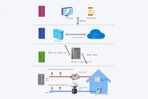
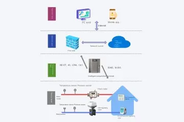
In municipal energy distribution, biochemical synthesis, and petrochemical refining, heat exchange is rarely a standalone process. Systems require highly integrated sub-stations designed to monitor, regulate, and distribute thermal energy dynamically under variable load configurations.
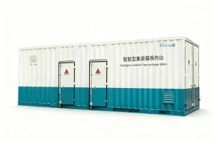
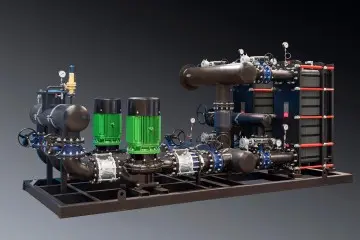
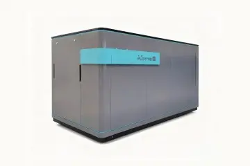
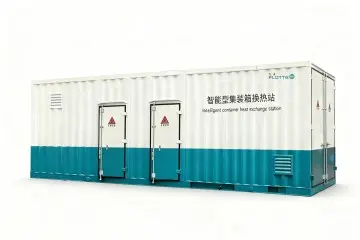
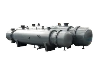
For municipal central heating projects, Flotte manufactures Modular Integrated Box-Type Heat Exchanger Units. These compact packages integrate the plate heat exchangers, variable frequency secondary circulating pumps, expansion tanks, and automated hydraulic balance loops inside a soundproof, weather-resistant structural frame, reducing installation timelines by up to 60%.
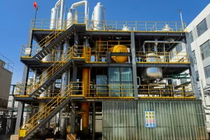
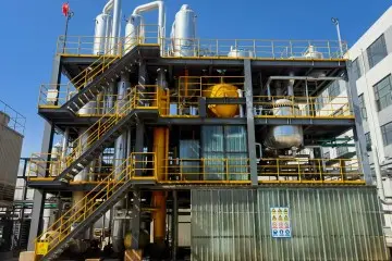
In chemical concentration and zero-liquid discharge (ZLD) plants, thermal economy is maximized through multi-stage configurations. Flotte's Multi-Effect Evaporation Systems route the boiled vapor from one effect to serve as the heating medium in the subsequent plate pack, optimizing latent heat recovery and significantly reducing steam consumption.
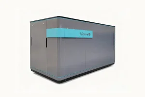
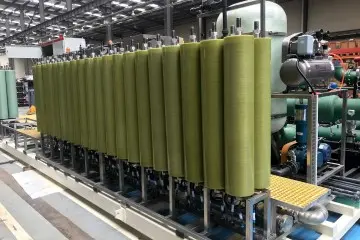
For sensitive liquid desalination, wastewater remediation, and food processing, we integrate specialized Membrane Concentration Systems alongside our thermal loops. Sizing calculations account for cross-flow velocities, transmembrane pressure, and heat-induced viscosity changes to prevent membrane scaling and premature wear.
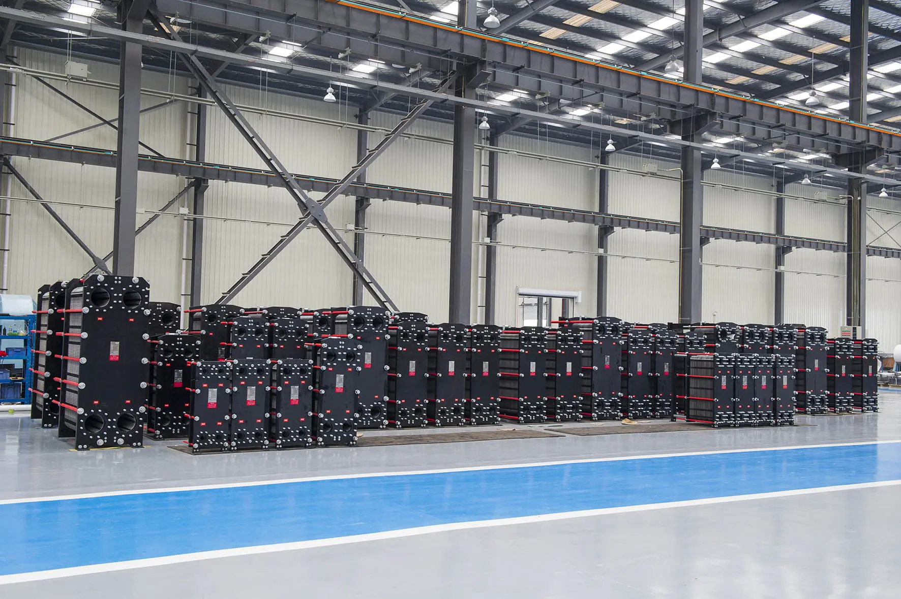
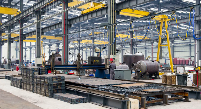
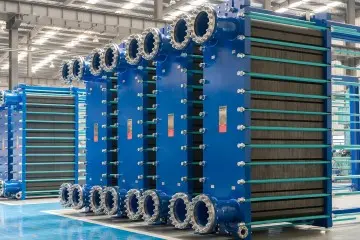
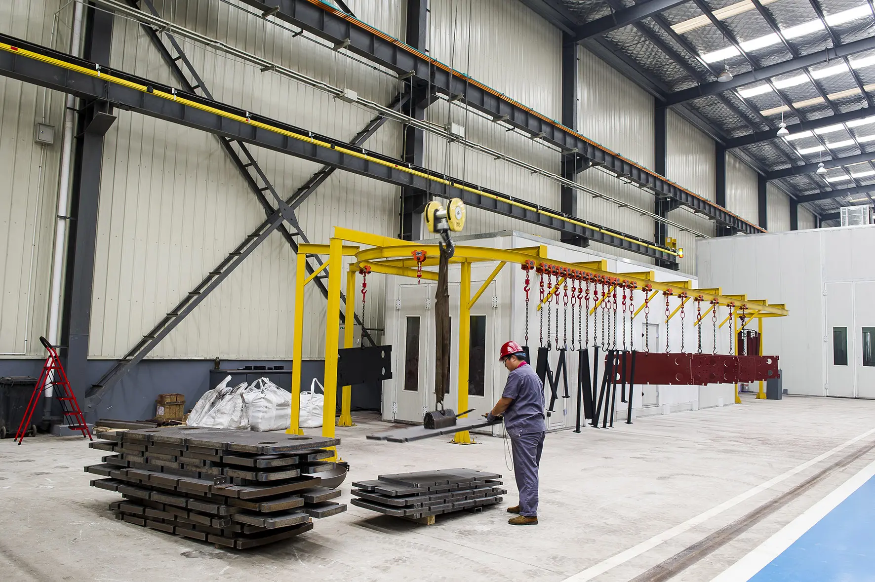
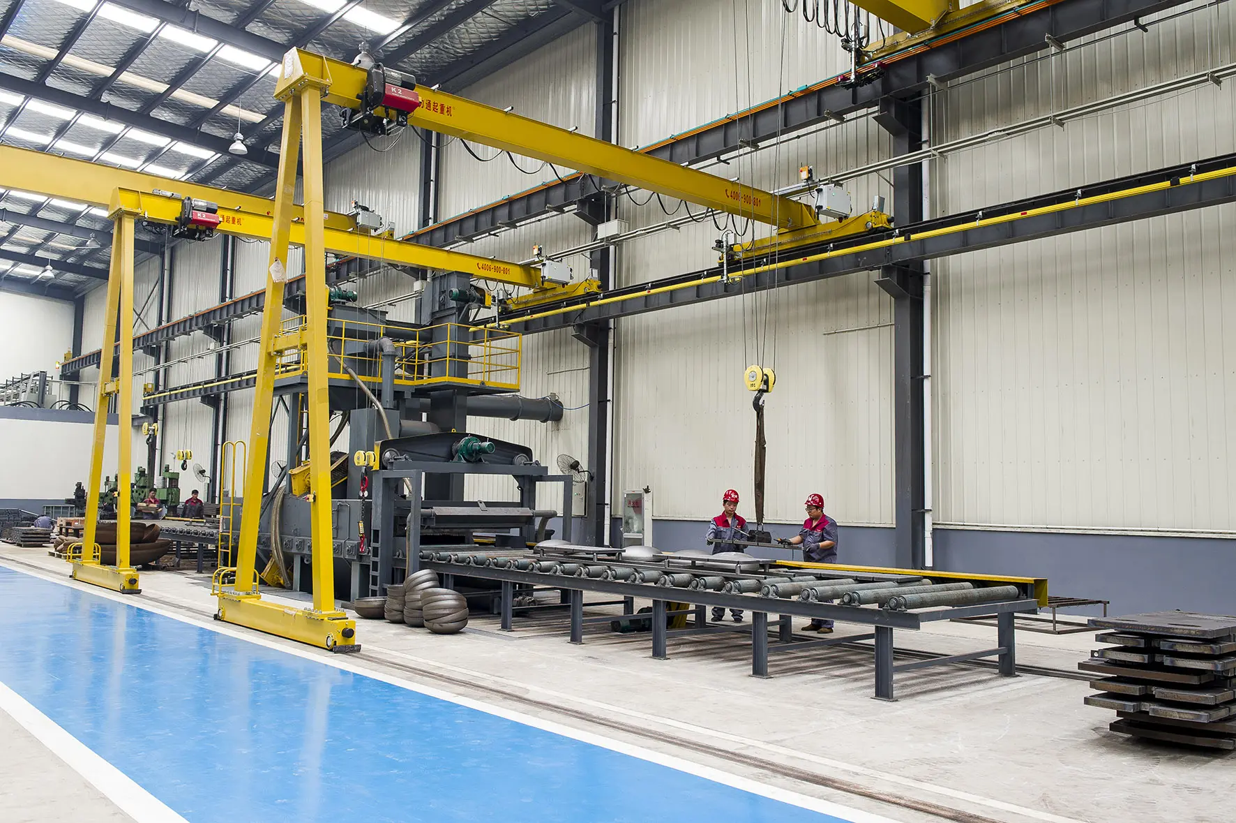
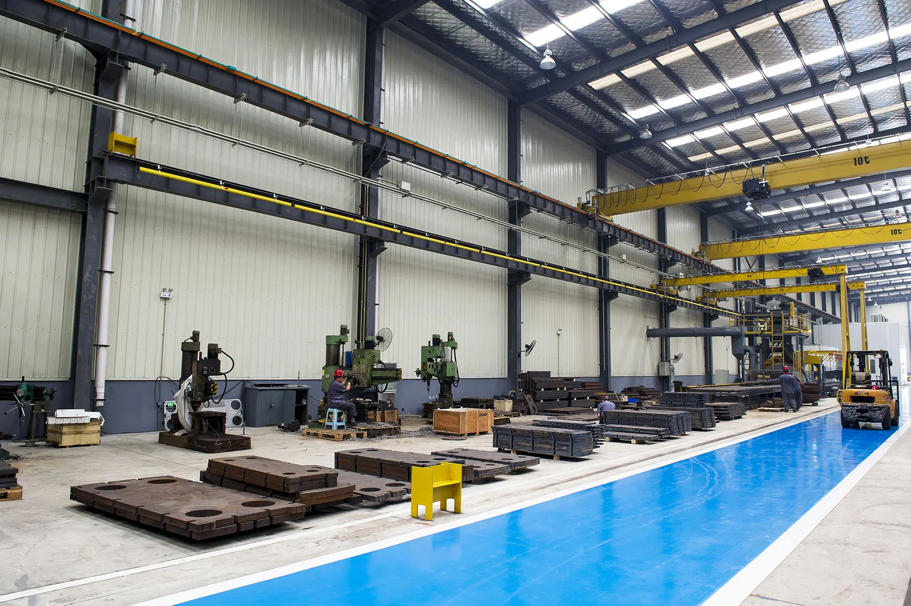
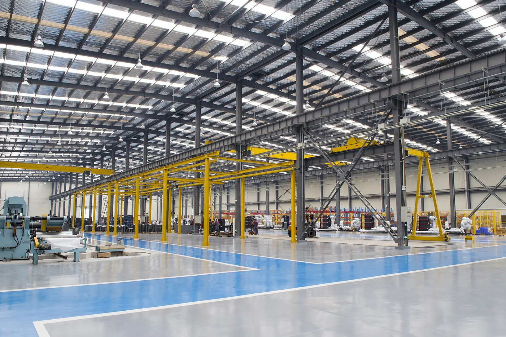
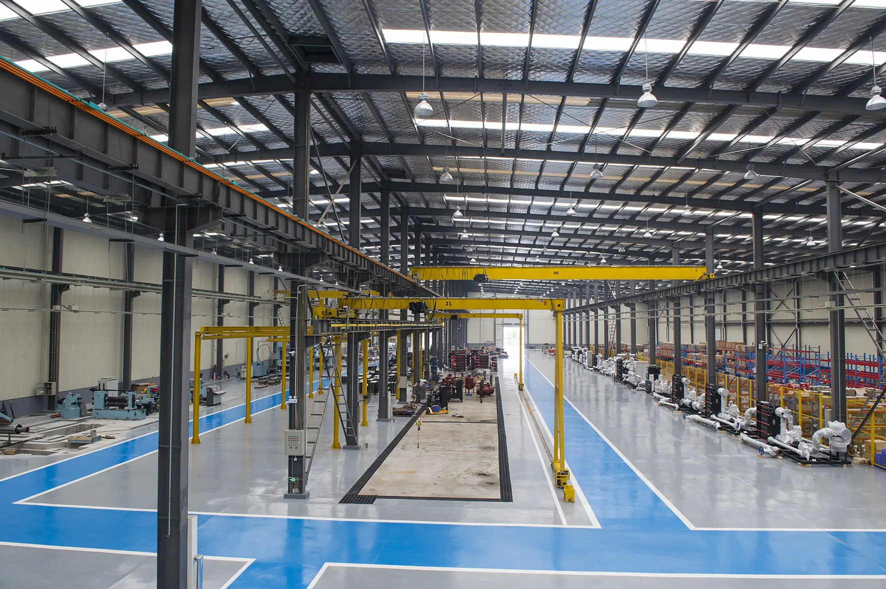
Each plate heat exchanger unit undergo a series of strict production processes from raw sheet metal handling to hydraulic testing to ensure long-term pressure vessel reliability.
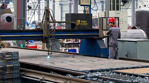
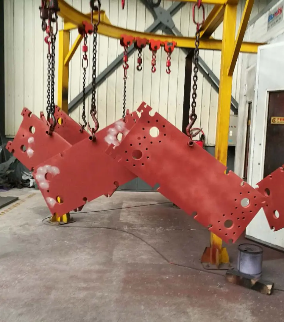
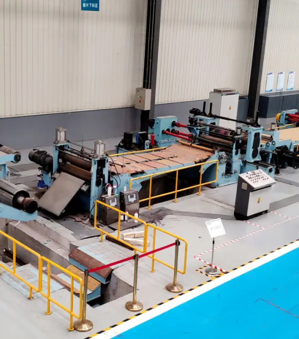
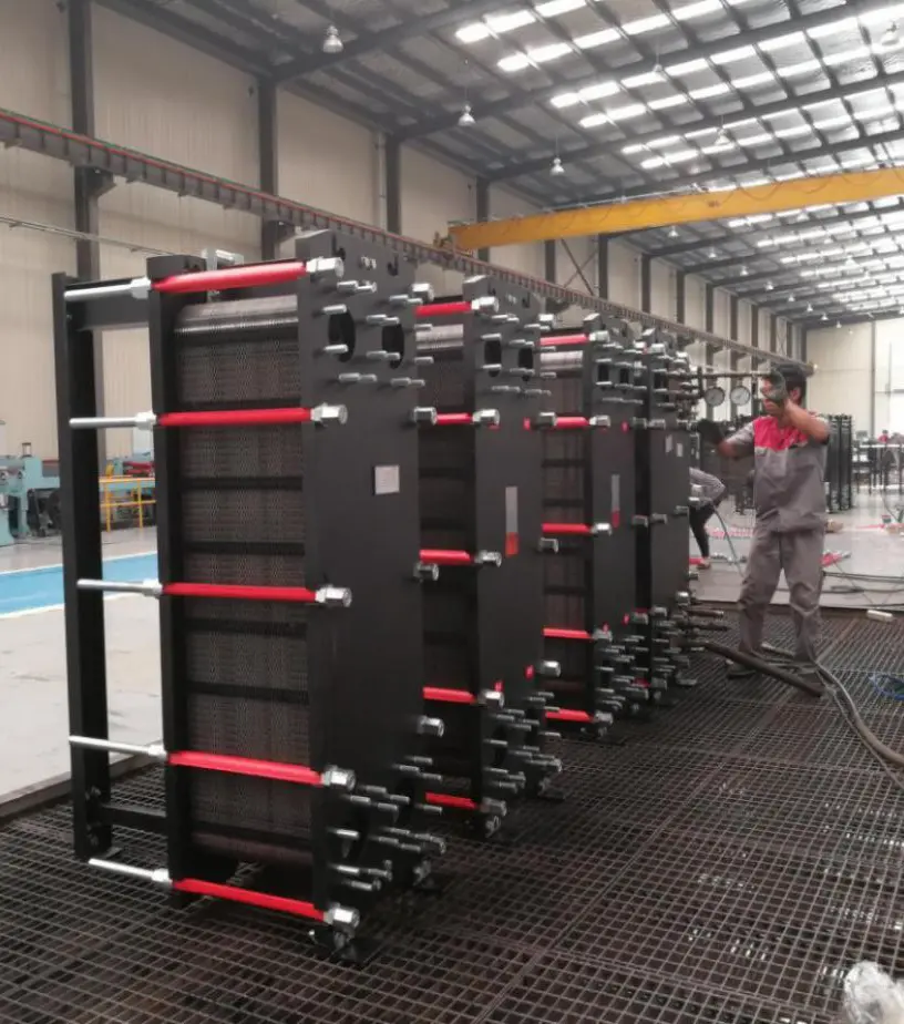
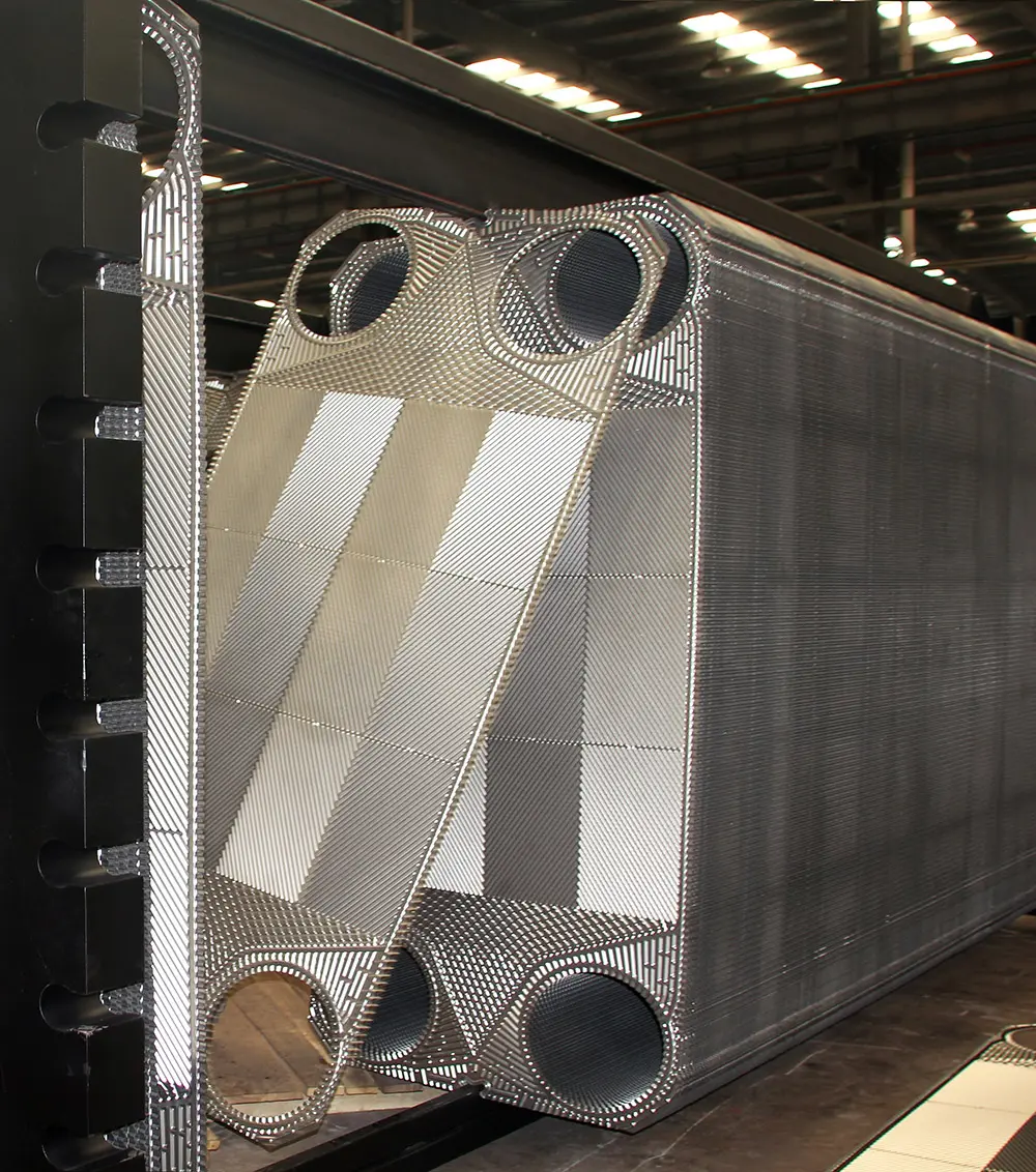
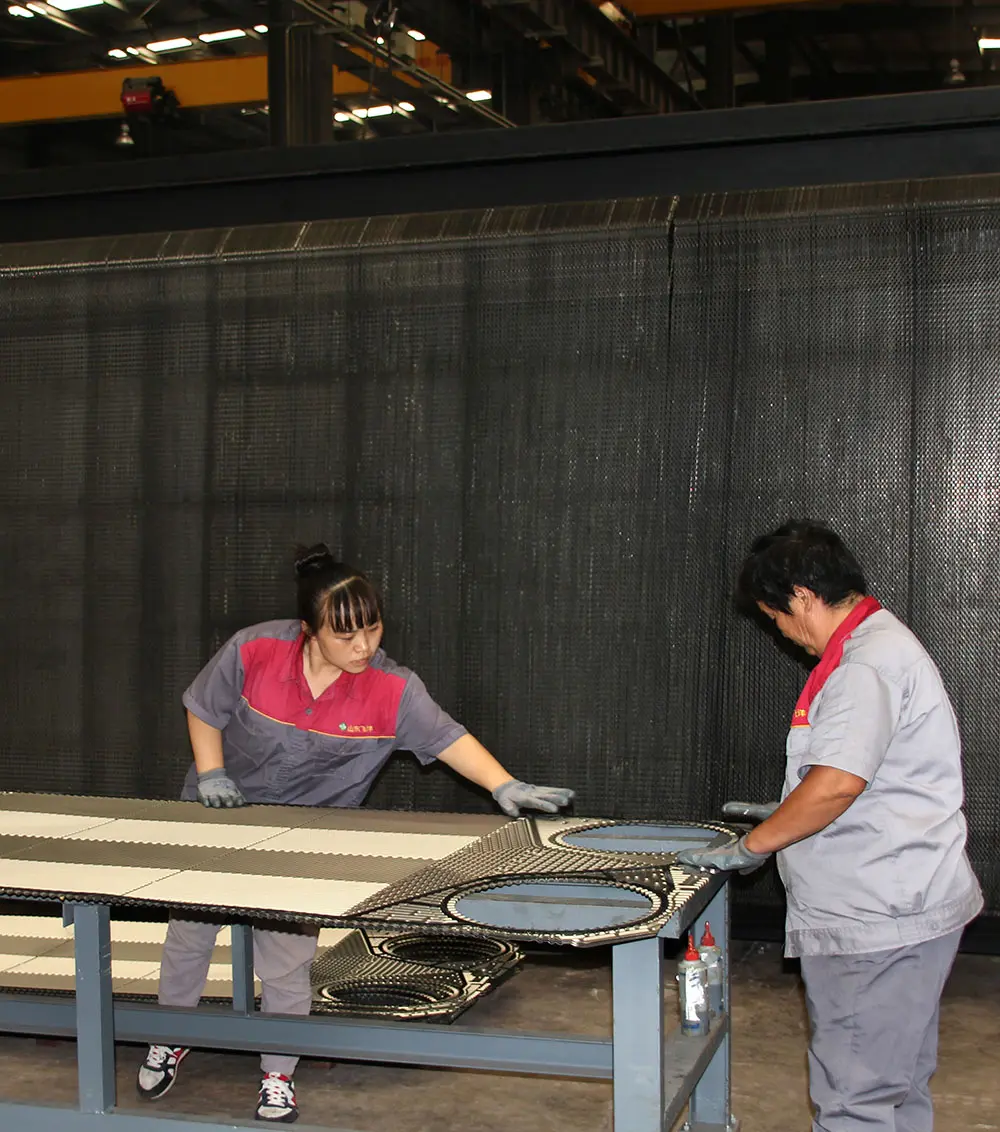
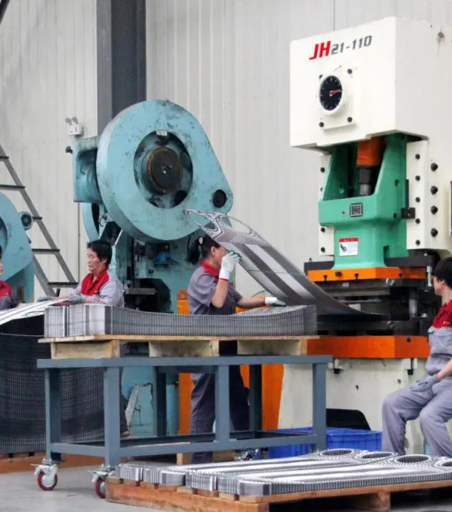
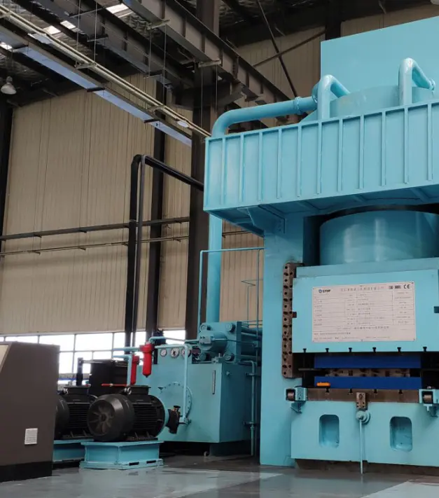
Each unit manufactured at Flotte aligns with high international safety standards. Our facilities operate under strict ISO 9001:2015 quality guidelines and conform to national pressure vessel standards. To meet the requirements of international procurement projects, we facilitate raw material chemical analysis (PMI), ultrasonic thickness monitoring, hydrostatic load testing up to 2.5 MPa, and dye penetrant crack verification.
By coordinating with third-party inspection firms (such as SGS or TÜV), we provide complete certification files, including material test reports (MTR) according to EN 10204 3.1, hydrostatic certificates, and design calculation sheets.




As industry shifts toward decarbonization and high-efficiency heat pumps, conventional sizing software often fails to account for low temperature gradients and complex fluid properties. Flotte's roadmap addresses these challenges through the integration of digital twin simulation models and machine learning-assisted design iterations.
By training neural networks on multi-variable performance logs, our systems optimize plate thickness and chevron geometries for high heat transfer rates under minimal pressure drop limits.
Real-time scaling detection systems adjust temperature profiles dynamically to mitigate bio-fouling and chemical scaling before performance drops occur.
Integrating mechanical calculations with hydraulic systems lets plants monitor pressure variations and forecast seal degradation patterns in advance.
The chevron angle (θ) dictates the degree of turbulence and resistance inside the flow channel. High chevron angles (e.g., 60° to the vertical) create high turbulence, raising the Nusselt number and convective heat transfer coefficient ($h$), but causing a substantial increase in pressure drop. Low chevron angles (e.g., 30° to the vertical) provide lower flow resistance and pressure drop, but yield lower heat transfer coefficients.
Our engineers use mixed-angle plate configurations (high and low channels in alternating sequences) to optimize the heat transfer area while remaining within the customer's maximum pressure drop limits.
For municipal closed heating loops, we recommend a design fouling factor ($R_f$) of 0.0001 to 0.0002 m²·K/W. Using excessive fouling safety margins can lead to over-sizing. Over-sized units reduce actual channel velocity below critical thresholds, which increases the accumulation of suspended solids and accelerates fouling.
The Logarithmic Mean Temperature Difference (LMTD) method is ideal when all inlet and outlet temperatures are known. For complex multi-pass flows, asymmetric flow rates, or when predicting outlet temperatures of an existing plate configuration, the Number of Transfer Units (NTU) or Effectiveness-NTU method is preferred, as it relies on thermal capacity ratios to determine performance limits.
The conduction resistance of the plate wall is represented by $\delta/k_p$. While thinner plates (e.g., 0.5 mm) improve the overall U-value and reduce material costs, they lower the maximum pressure rating. For high-pressure steam applications or aggressive environments, a thicker plate (0.6 mm or 0.7 mm) is required to ensure mechanical stability, even if it slightly reduces the heat transfer coefficient.
We use high-grade EPDM, NBR, or Viton gaskets with clip-on designs that sit securely within the plate grooves. Before shipment, every assembled plate pack undergoes dual-stage hydrostatic pressure testing at 1.3 to 1.5 times the design pressure, verifying seal integrity and preventing cross-contamination under variable load operations.
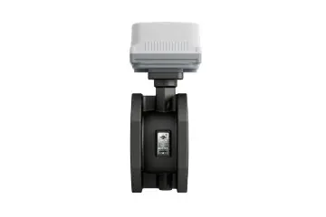
Specialized thermal concentration systems, membrane desalination loops, and precision flow monitoring solutions for industrial processes.
 Flotte Energy