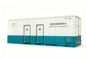
Explore our premium grade fluid-control and heat transfer systems engineered for high efficiency and extreme operating conditions.

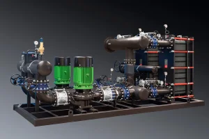
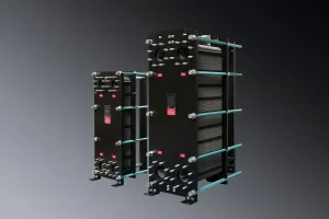
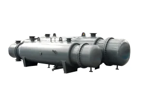
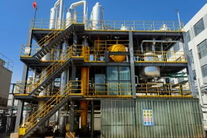
Flotte Energy Saving Company, formally established in 2013 with a robust registered capital of 101 million yuan, traces its direct engineering roots to Flotte Thermal Engineering, founded in 1995. For nearly three decades, we have continuously led the development of thermal exchange systems, industrial water treatment installations, and advanced HVAC configurations.
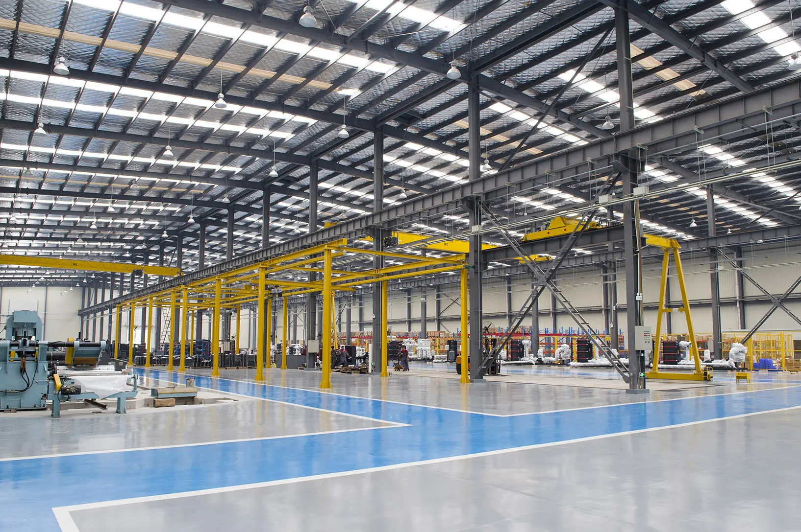
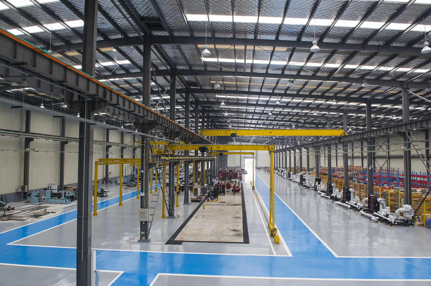
With modern manufacturing plants sprawling across a vast 70,000 square meters area, Flotte represents a vital hub for engineering, manufacturing, and global exporting. We produce over 4,500 integrated heat exchange stations and high-precision fluid regulation systems annually, servicing thermal power stations, municipal heating networks, pharmaceutical facilities, and chemical industries globally.
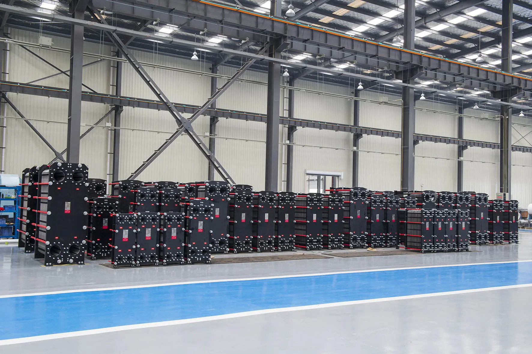
Comprehensive engineering methodology for calculating heat transfer, pressure drops, and shear stress inside corrugated plate channels.
"In the domain of advanced thermal system design, selecting the optimal configuration for a Plate Heat Exchanger (PHE) requires an exact balance between heat transfer rates, allowable pressure drop thresholds, and shear stress profiles. Empirical calculations packaged within our downloadable calculation PDFs serve as the engineering blueprint for industrial system integrators worldwide."
The basic governing thermodynamic equation utilized in our engineering software and summarized in our Plate Heat Exchanger Calculation PDF relies on the fundamental heat transfer relation:
Where Q represents the total heat load in kilowatts (kW), U represents the overall heat transfer coefficient (W/m²·K), A is the effective heat transfer surface area (m²), ΔTlm is the Logarithmic Mean Temperature Difference, and F is the LMTD correction factor, which accounts for non-pure counter-current flows typical in multi-pass plate arrangements.
Determining the overall heat transfer coefficient (U) requires detailed calculation of the individual film coefficients on both hot and cold channel faces, along with the thermal resistance of the metallic plate materials and fouling layer margins:
In this formula:
The fluid dynamics within the corrugated channels directly dictate the heat transfer efficiency. The Reynolds number (Re) calculations within our thermal design engine are calculated as:
where G represents the channel mass velocity (kg/m²·s), De is the equivalent channel hydraulic diameter (typically equal to twice the plate corrugation press depth), and μ is the fluid dynamic viscosity. The flow inside corrugations becomes turbulent at remarkably low Reynolds numbers (Re > 10 to 150 depending on the chevron pattern angle). This early turbulence generation is what allows plate heat exchangers to achieve heat transfer coefficients 3 to 5 times larger than traditional shell and tube exchangers.
However, the intense turbulent mixing introduces significant pressure drop costs. Our design engineers balance this trade-off using the Fanning friction factor, carefully configuring plates with high-chevron angles (theta > 45°, offering high heat transfer rates but high pressure drop) and low-chevron angles (theta < 30°, offering lower heat transfer and lower pressure drop) to align with maximum pump capacities.
Analyzing key structural transformations in manufacturing, material procurement, and localized compliance.
The global thermal energy sector is transitioning from manual calculation sheets to cloud-based thermal design software integration. Instantaneous access to PDF design parameters, dynamic calculation reports, and 3D CAD modeling allows global procurement departments to speed up project execution timelines. Flotte's R&D center provides complete technical validation to assure zero errors during design integration.
Decarbonization goals demand materials with minimal environmental impact. Our high-grade stainless steels, Hastelloy configurations, and Titanium alloys are sourced under strict environmental tracking. Efficient plate design translates to lighter structural footprints, reducing raw material utilization by up to 40% compared to legacy designs.
Global engineering firms require equipment that adheres to domestic and international pressure standards. Flotte satisfies these compliance needs by certifying our production lines under ASME Section VIII, European Pressure Equipment Directive (PED) 2014/68/EU, and national Chinese GB150 guidelines. This double-layer safety protocol guarantees seamless integration in all regions.
Global Sourcing Tip: When obtaining a plate heat exchanger calculation sheet, always verify that the supplier has accounted for fluid viscosity changes under peak operating temperatures. Failing to factor in temperature-dependent viscosity changes often results in inadequate motor sizing and excessive pressure drop penalties in real-world configurations.
A closer look inside Flotte's vertical production workflow. From structural steel cutting to water pressure validation, quality is engineered into every stage.
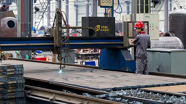
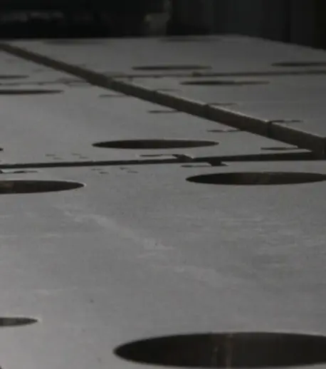
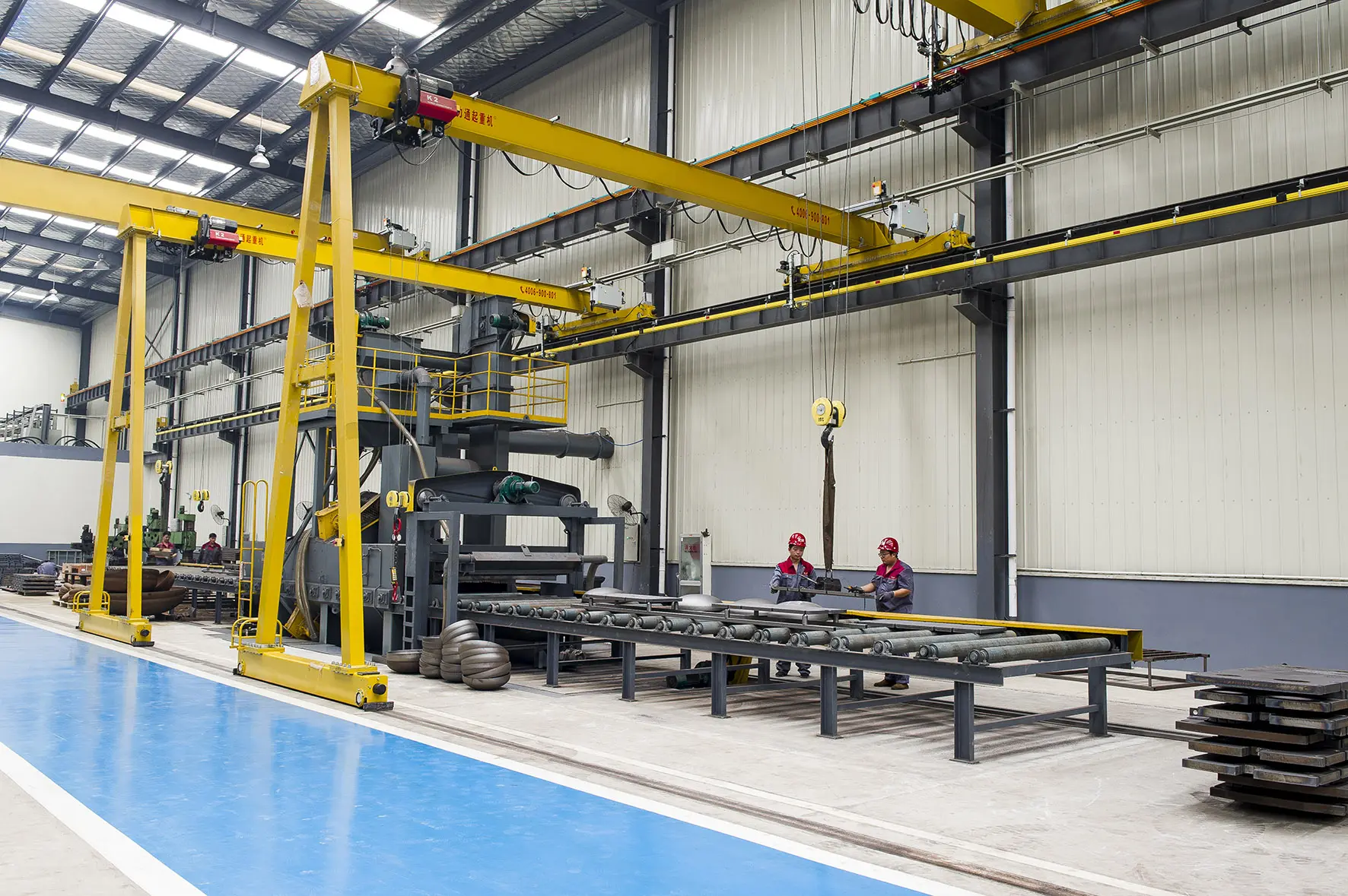
Precision oxygen-cutting and plasma systems shape the thick structural frame plates of the heat exchangers.
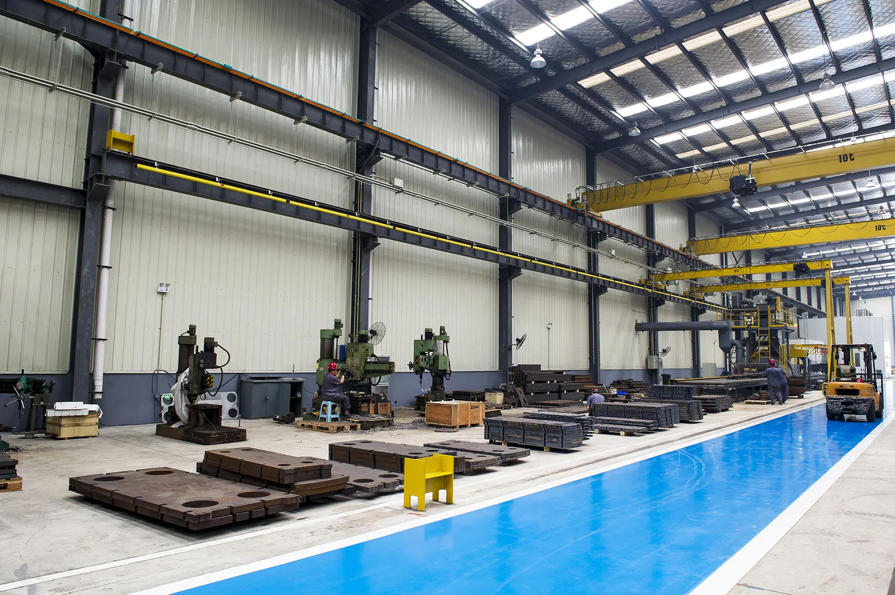
Specialized micro-level forging machinery forms the critical load-bearing structural connections and connection ports.
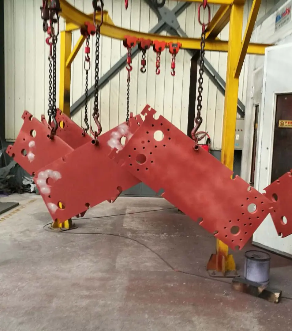
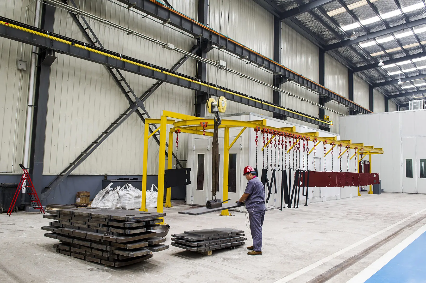
Multi-layered anti-corrosion coatings applied to structural steel surfaces ensure long operational lifespans in humid environments.
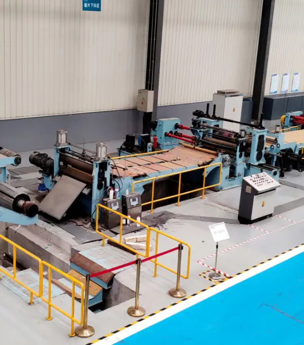
Alloy sheets are cut to size and laser coded for full traceability of material composition back to the mill batch.
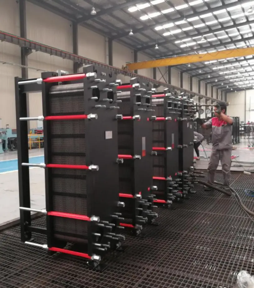
Each unit undergoes strict hydrostatic pressure testing (up to 1.5 times the design limit) to verify zero internal bypass leaks.
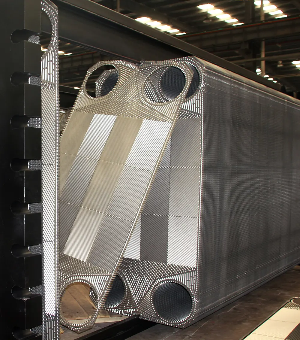
Precision tightening of alignment guide bars by certified assemblers prevents uneven gasket compression.
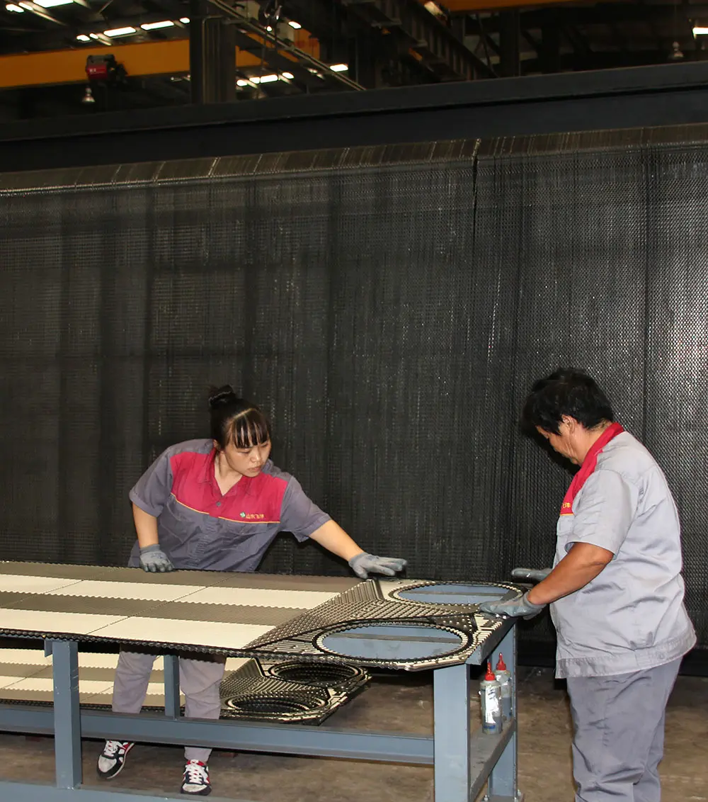
Strict application of high-temperature NBR/EPDM elastomeric gaskets guarantees a reliable, leak-free seal.
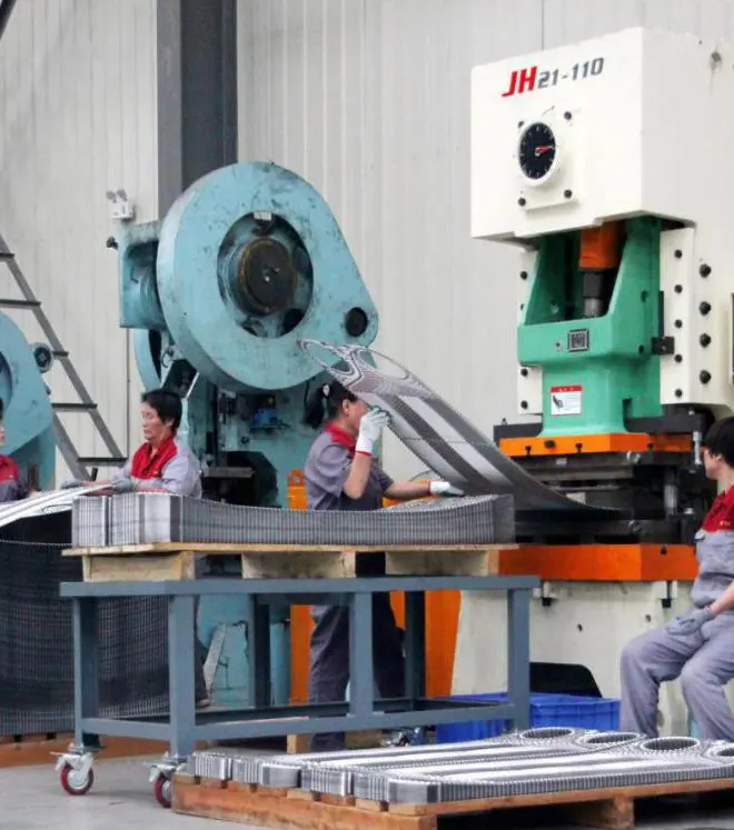
CNC punch lines punch alignment slots and fluid connection ports through the stainless steel plates.
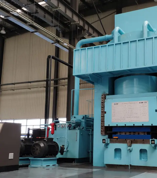
Massive 10,000-ton hydraulic presses press the chevron flow channels into the metal plates in a single strike to prevent stress fractures.
Our plate heat exchangers carry certified quality marks and pressure safety registrations, meeting the requirements of international procurement projects.
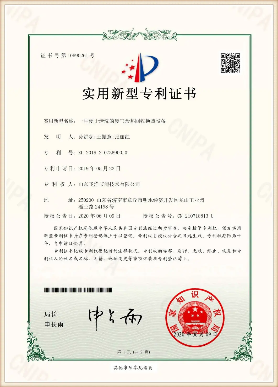
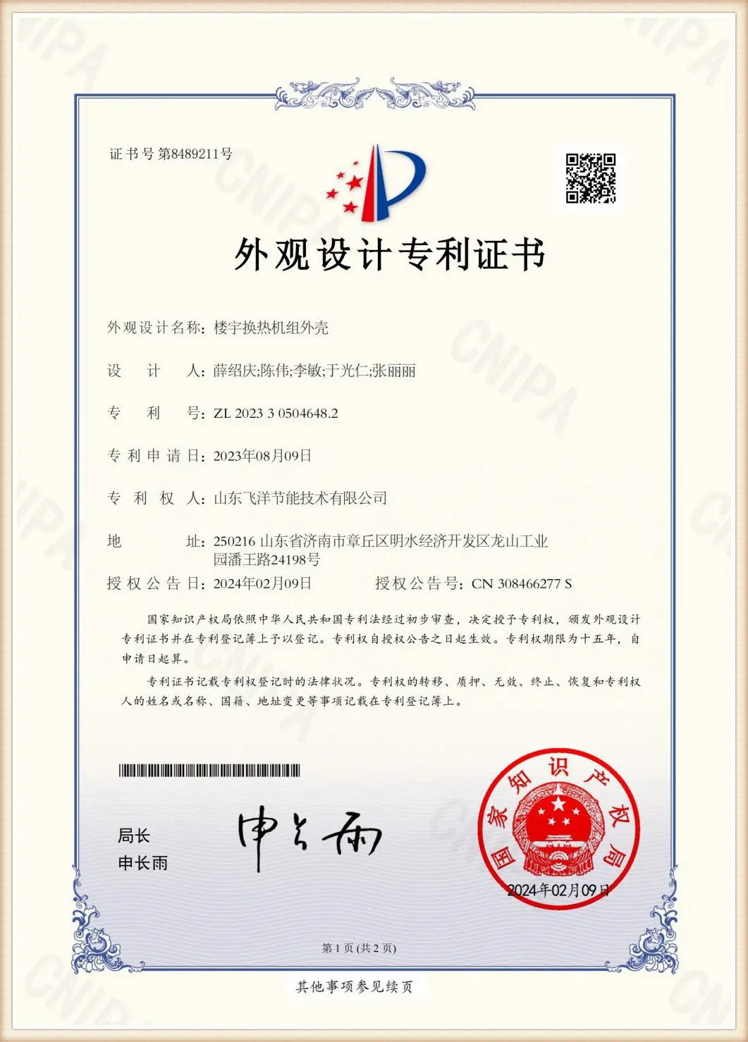
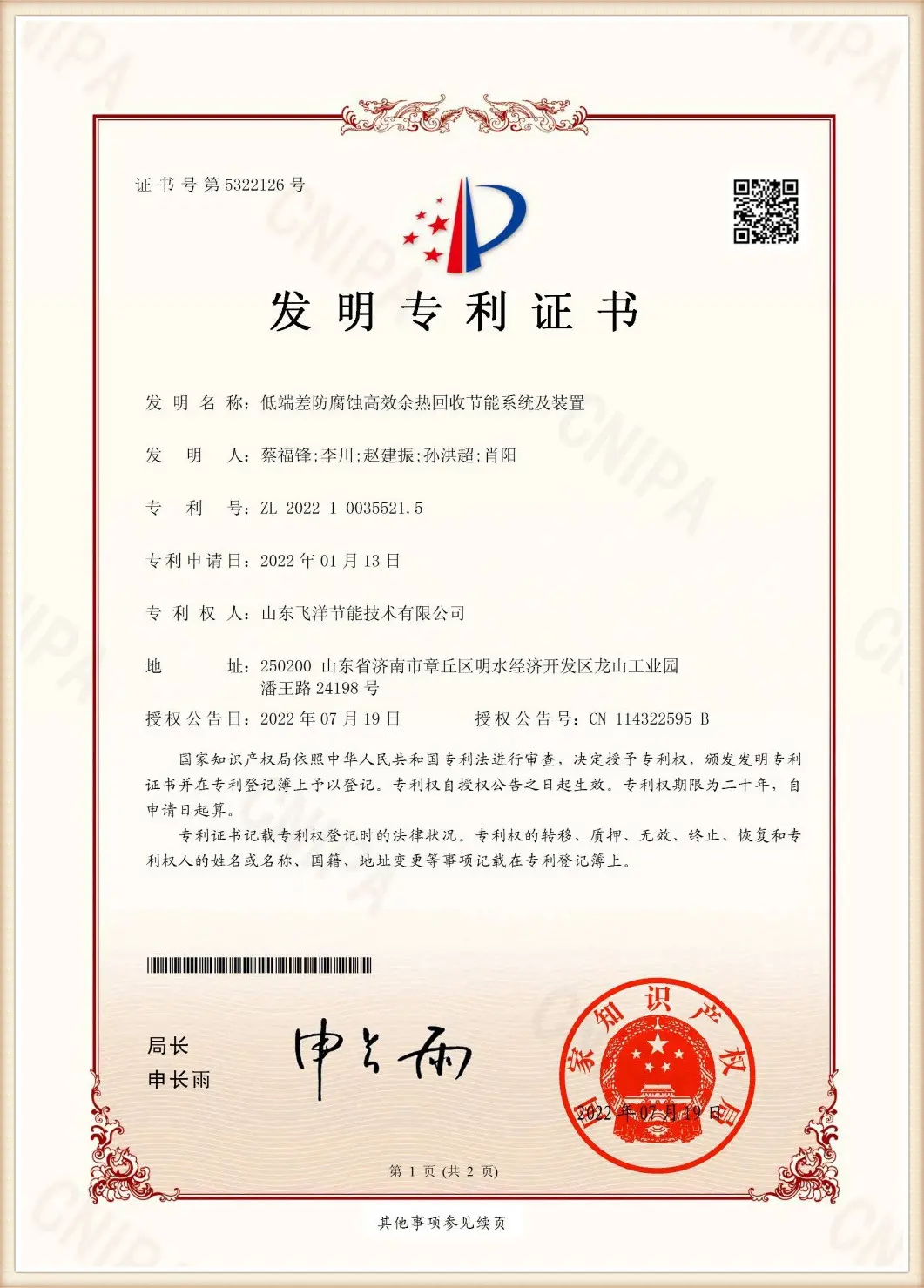
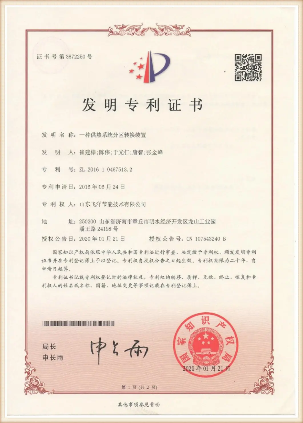
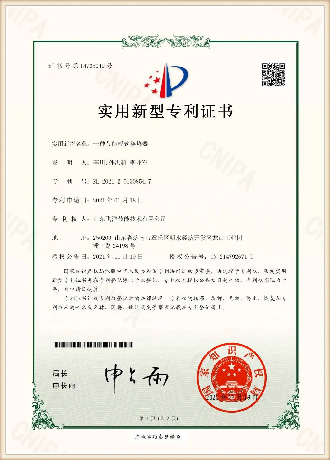
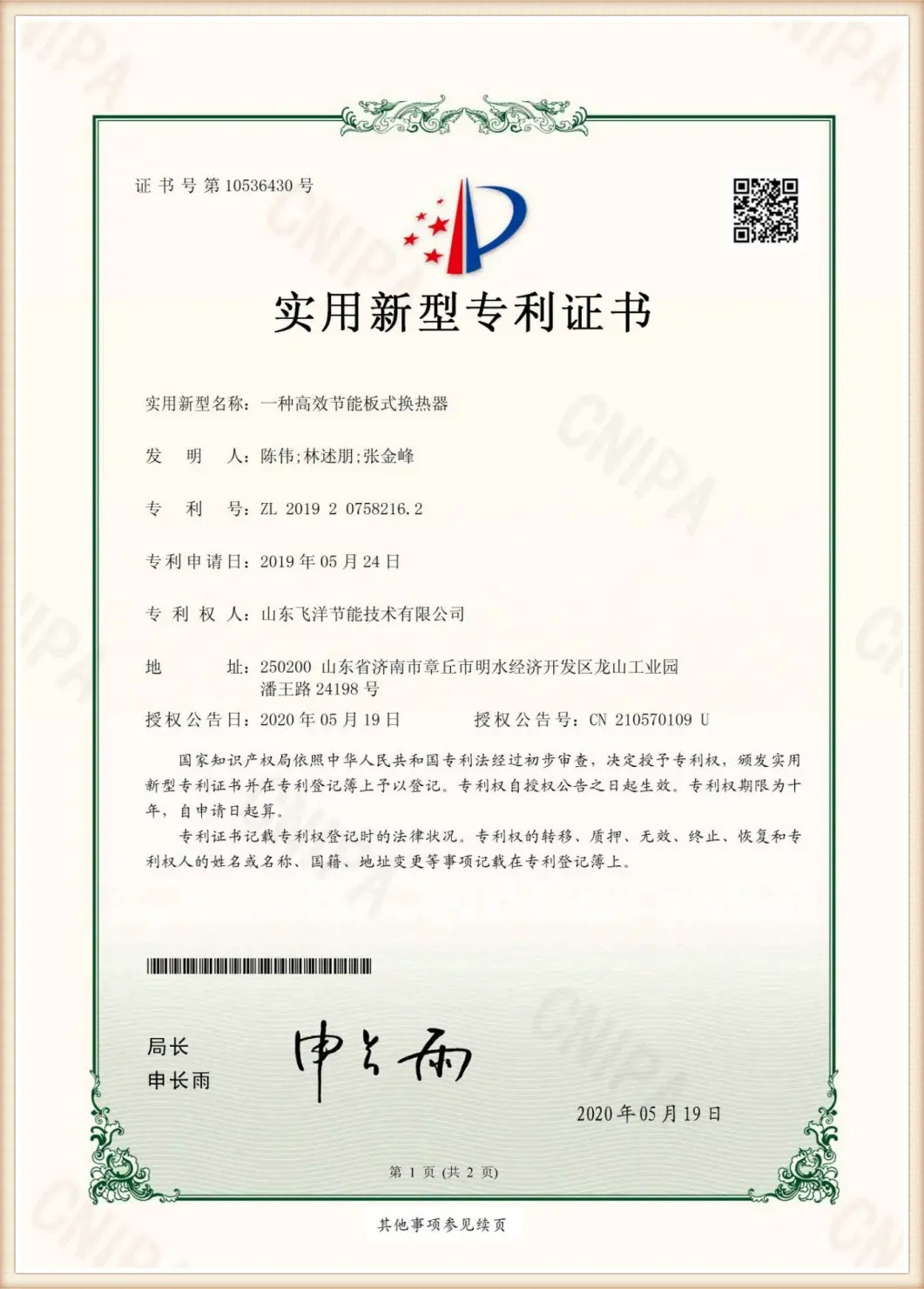
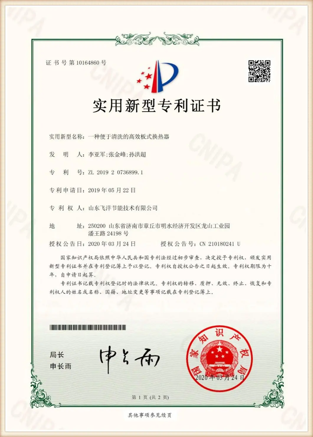
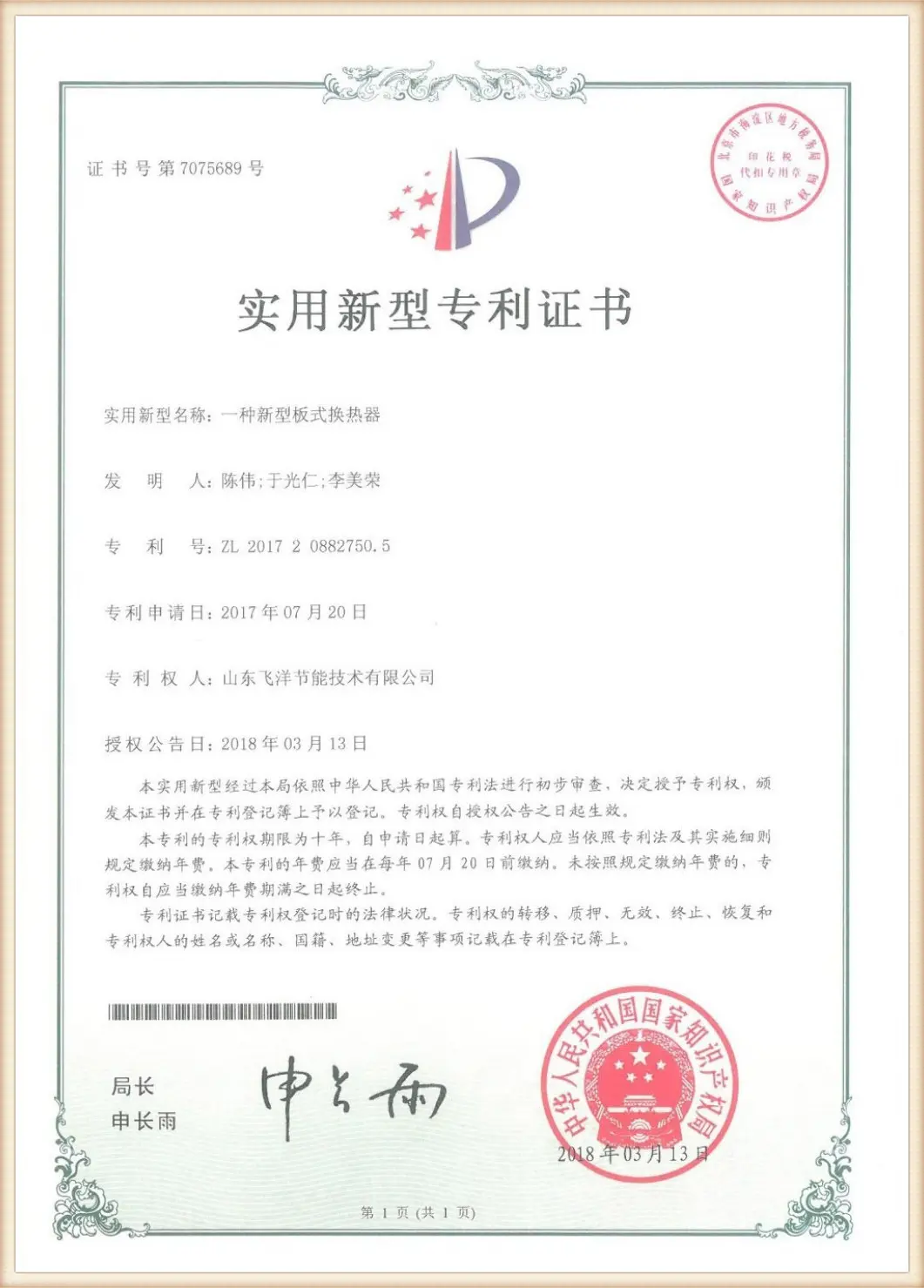
A look at our CNC pressing lines, high-precision assembly tooling, and clean rooms that support our large-scale production runs.



Providing specialized thermal management configurations to meet high-performance industrial requirements.
In municipal central heating schemes, plate heat exchangers act as the primary interface between high-pressure primary networks and domestic heating loops. Precision sizing is critical here: a minor discrepancy in calculations can lead to low return temperatures at the municipal plant, affecting overall system performance. Flotte's intelligent heat exchange units adjust flow distribution using automated hydraulic balance valves, maintaining stable delivery temperatures across varying heating loads.
Chemical processing requires chemical-resistant plate metallurgy to handle aggressive acids and high operating temperatures. Standard calculation sheets must evaluate material degradation rates alongside fluid dynamics. Flotte offers specialized configurations using high-grade Titanium (Gr1/Gr2), Hastelloy C276, and Nickel alloys, paired with laser-welded cassettes to prevent corrosive fluid bypass.
Our future technology roadmap centers on reducing fouling layers (Rf) through surface modifications. Standard plates accumulate suspended solids and mineral deposits over time, which reduces the overall heat transfer coefficient (U).
Flotte's upcoming plate designs utilize micro-grooves that generate local micro-vortices at low velocities, creating a self-cleaning effect on the plate surface. This development is expected to reduce maintenance cleaning intervals by up to 50% in wastewater and process cooling applications.
Find technical answers on plate heat exchanger sizing, calculations, and performance parameters.
Discover our range of intelligent heat exchange units, energy efficiency valves, and advanced evaporation systems.
 Flotte Energy