Explore our foundational equipment deployed in industrial networks, municipal central heating, and high-efficiency water treatment.
A benchmark of quality, validation, and production volume in global heat exchange technologies.
Flotte Energy Saving Company, established in 2013 with a registered capital of 101 million yuan, originated from Flotte Thermal Engineering founded in 1995. With three decades of technical expertise, the company specializes in water equipment, HVAC systems, and water treatment industries. It consistently leads industry peers in adopting cutting-edge technologies, developing innovative products, and delivering comprehensive production and sales services.
With over 300 employees globally and advanced automated production complexes, the company generates annual sales revenue exceeding 500 million yuan, contributing over 15 million yuan in taxes and profits annually, reinforcing our role as a secure, long-term supply chain partner.
An authoritative engineering guide on calculations, fluid dynamics, and Chevron corrugation analytics.
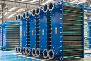
In modern process industries, municipal district heating grids, and complex cooling systems, the Plate Type Heat Exchanger (PHE) stands as the pinnacle of efficient thermal management. Designing a PHE requires balancing heat transfer optimization against pressure drop limitations. The core calculations focus on defining flow regimes, heat transfer coefficients, and structural reliability parameters, which are thoroughly detailed in our downloadable Plate Type Heat Exchanger Design Calculation PDF manual.
The total heat load ($Q$) of a plate heat exchanger is determined by the energy conservation equations of the primary and secondary fluids:
Q = mh * Cph * (T1in - T1out) = mc * Cpc * (T2out - T2in)
Where:
• mh, mc = Mass flow rate of the hot and cold fluids (kg/s)
• Cph, Cpc = Specific heat capacity (J/kg·°C)
• T1, T2 = Temperatures at respective inlet and outlet ports
Once the heat load is verified, the required heat transfer area ($A$) is derived using the general heat transfer equation:
A = Q / (U * ΔTlm * F)
Where U is the Overall Heat Transfer Coefficient, ΔTlm is the Logarithmic Mean Temperature Difference, and F is the LMTD correction factor. The Logarithmic Mean Temperature Difference is calculated as:
ΔTlm = [ (T1in - T2out) - (T1out - T2in) ] / ln[ (T1in - T2out) / (T1out - T2in) ]
Unlike shell and tube heat exchangers, plate heat exchangers generate highly turbulent flow even at low Reynolds numbers ($Re < 100$) due to the chevron angles pressed into the plates. The convective heat transfer coefficient ($h$) inside the channels is related to the Nusselt number:
Nu = h * Dh / k = C * Rem * Prn * (μ / μw)x
Here, the hydraulic diameter (Dh) is critical and is defined as 2b / Φ, where b is the mean channel spacing (corrugation depth) and Φ is the plate enlargement factor. The chevron angle (θ) dictates the constant values of C, m, and n. Plates with high chevron angles (e.g., 65°) offer superior heat transfer coefficients but generate higher pressure drops, whereas low chevron angles (e.g., 30°) have lower resistance but reduced thermal efficiency.
Engineers must ensure that calculated pressure drops do not exceed the design limitations of the pump systems. The channel pressure drop is represented as:
ΔP = f * (Lp / Dh) * (ρ * v2 / 2)
Where:
• f = Friction factor (determined by chevron angle and Reynolds number)
• Lp = Port-to-port plate length
• v = Channel fluid velocity
• ρ = Density of the fluid
Iterative calculation algorithms balance thermal length (NTU) with allowable pressure drops to determine optimal plate pack distribution.
Incorporates precise margins to counter biofouling and scale buildup, assuring long-term operations across thermal power and chemical sectors.
Ensures mechanical calculations meet structural requirements for high pressure ratings, verified by national boiler safety standards.
How Flotte's plate heat exchanger specifications adapt to regional climates and processes.
Plate heat exchangers must be configured for the localized conditions where they operate. Using standardized calculations without adapting to local environments can lead to thermal deficits or premature equipment failure. Below are three primary localized application scenarios where Flotte's customized thermal engineering calculators provide critical support:
In sub-zero winter temperatures, municipal heating networks require highly optimized Intelligent Heat Exchange Units. Design calculations must account for high viscosity of cold return water, demanding larger port configurations to prevent localized freezing and optimize flow distribution across municipal grids.
In environments operating Membrane Concentration Systems, the primary fluid is corrosive seawater. Calculation PDFs must focus on Titanium or Hastelloy plate options, with specific equations adjusted for high salinity, determining exact fouling allowances to prevent salt precipitation along the chevron valleys.
Highly regulated building HVAC systems require strict energy recovery margins. Design calculations must utilize high NTU (Number of Transfer Units) configurations to achieve close temperature approaches (less than 1°C), directly reducing building energy consumption and satisfying modern green building certifications.
Bridging traditional thermodynamic calculations with modern AI monitoring and manufacturing automation.
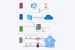
The heat transfer industry is transitioning from static sizing calculators to dynamic, sensor-integrated thermal management solutions. Flotte’s R&D center is leading this evolution by integrating mechanical design calculations with real-time field operations:
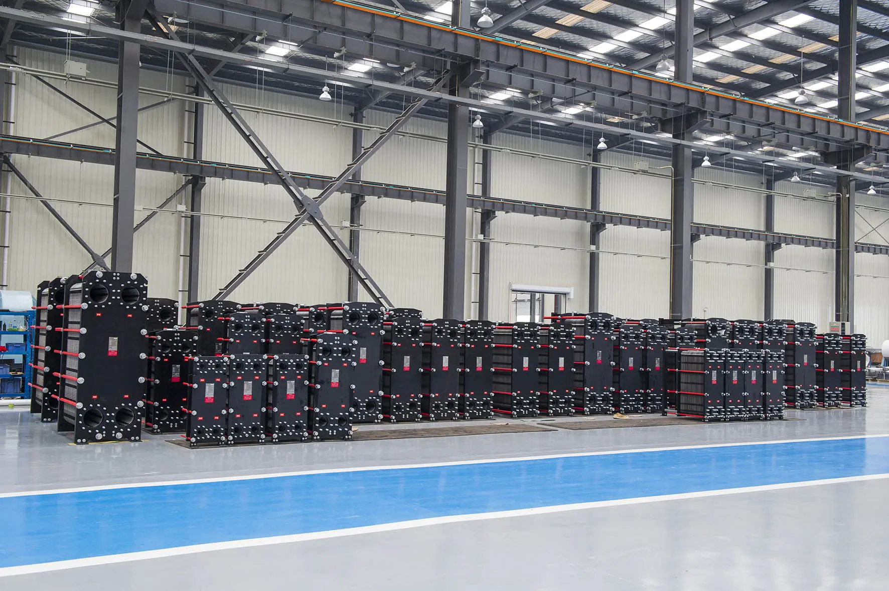
Unmatched manufacturing speed, cost efficiency, and rigorous quality control protocols.
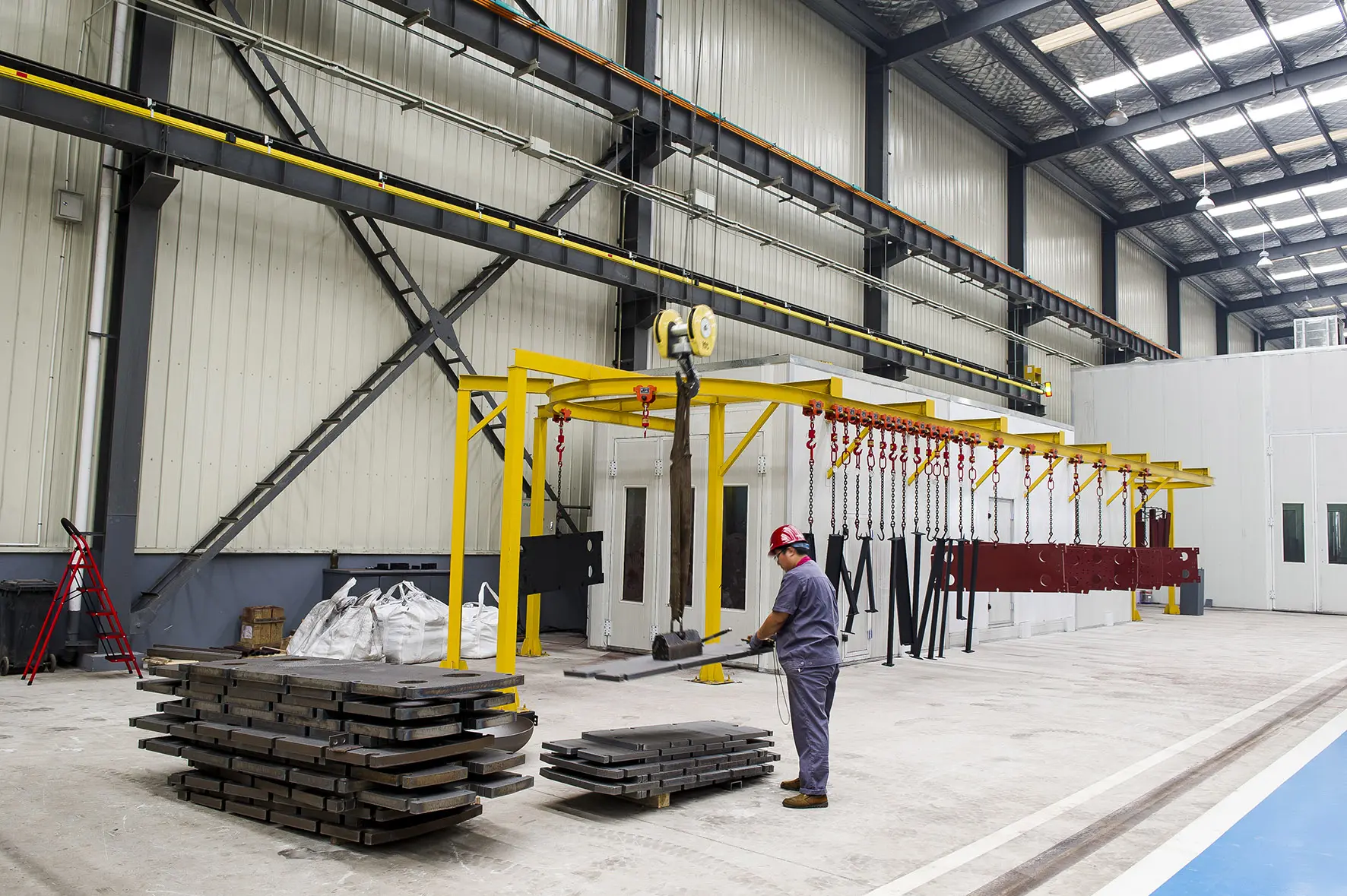
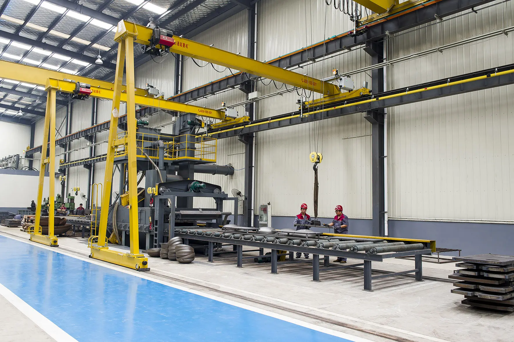
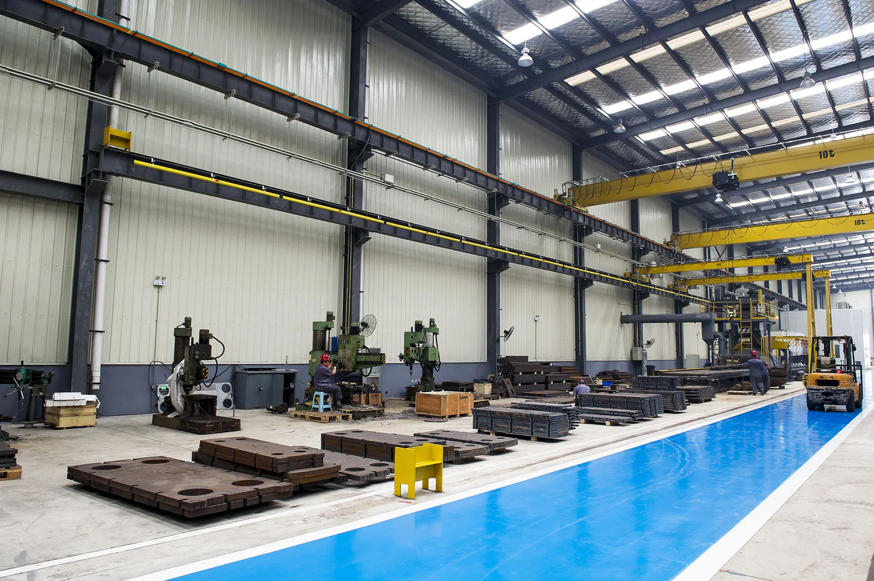
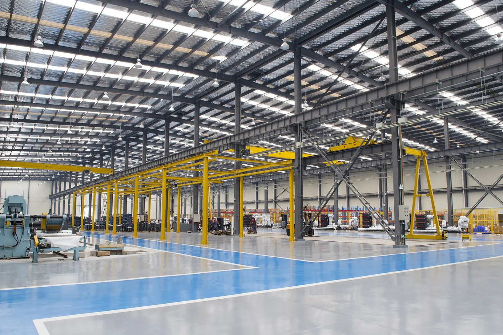
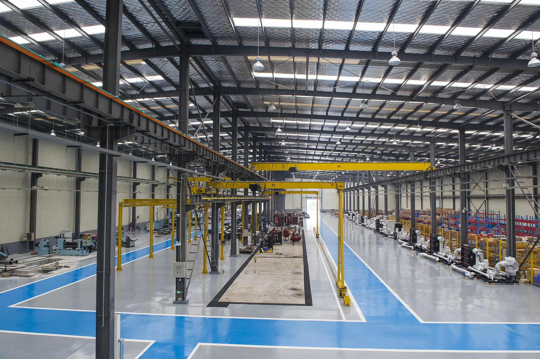
Operating from our modern 70,000 square meter industrial park, Flotte leverages China's robust industrial ecosystem to deliver reliable thermal equipment worldwide. Our vertically integrated production process guarantees high precision, fast lead times, and stable pricing, even during global supply chain fluctuations.
We source premium stainless steel, titanium, and specialized rubber compounds from verified partners. This direct link protects our clients from pricing volatility and material delays.
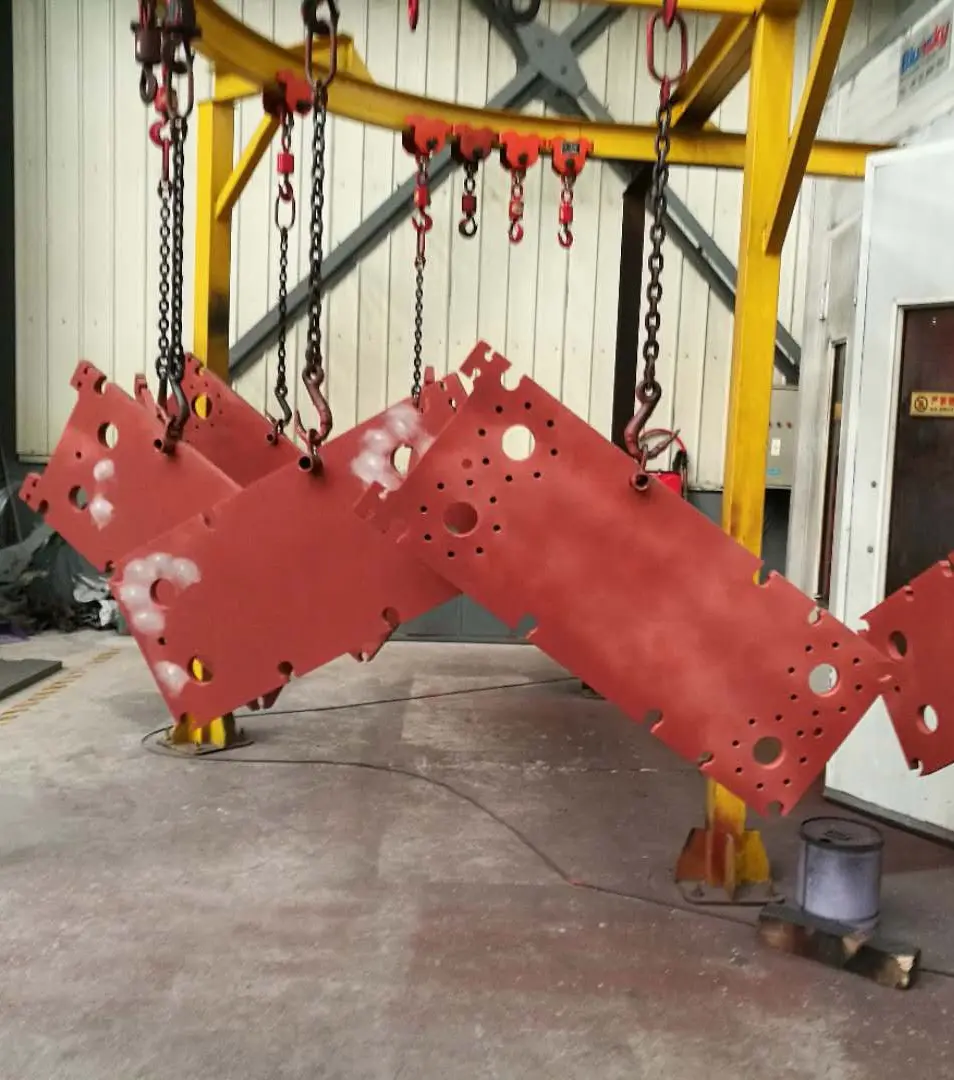
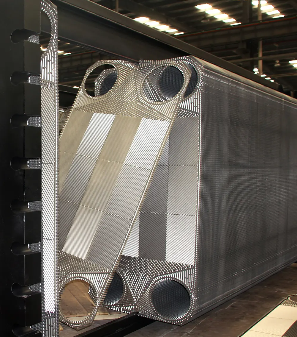
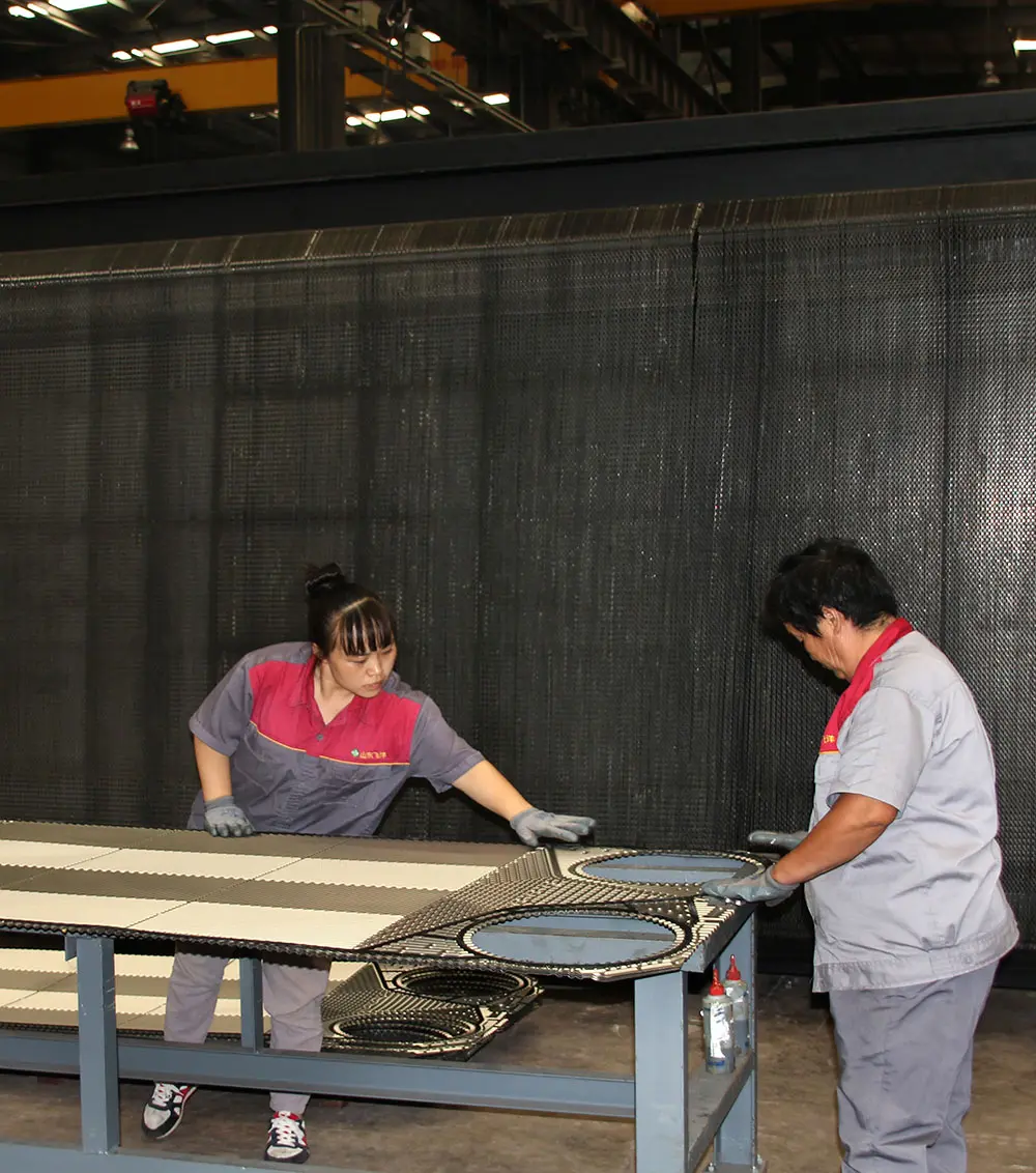
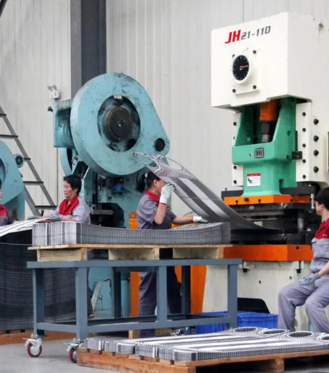
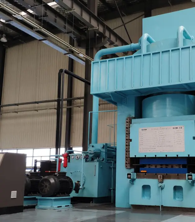
Our facility houses massive hydraulic presses that stamp out heat exchanger plates with millimeter-level accuracy, maintaining consistent channel geometry and corrugation depths.
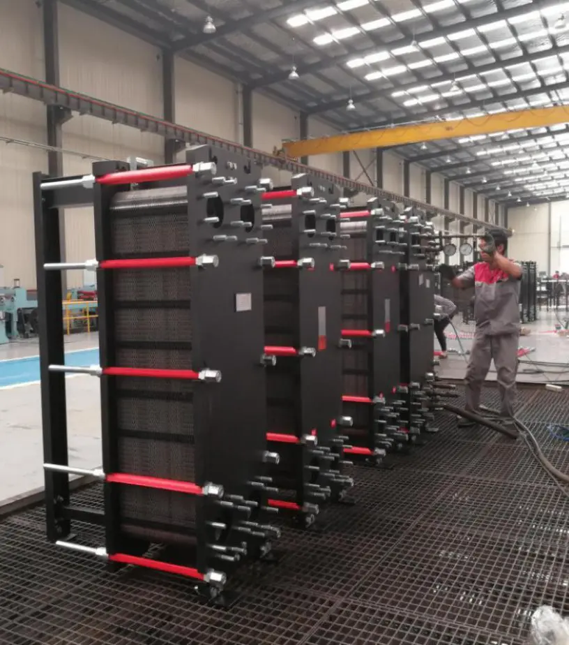
Every plate pack undergoes hydrostatic and helium leak testing before shipment. All products adhere to ISO 9001, ISO 14001, and ISO 45001 international standards.
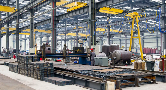
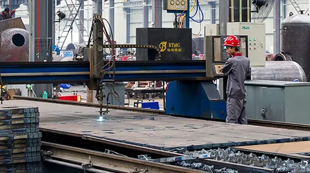
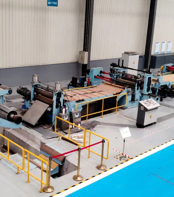
From raw plate cutting to final pressure testing, transparency and excellence guide our assembly floor.
Adapting thermal solutions to meet international decarbonization goals and energy efficiency metrics.
Industrial organizations globally face rising pressure to reduce energy consumption and operational carbon emissions. Plate heat exchangers are critical tools in this effort, enabling high-efficiency waste heat recovery that was previously cost-prohibitive. From processing facilities in Europe to energy projects in North America, thermal efficiency is now a core requirement for regulatory compliance and economic viability.
Flotte's plate heat exchangers and intelligent energy systems are designed to address these requirements. By utilizing our detailed design calculation tools, global project teams can size systems to minimize energy footprint, reduce pump loads, and extend maintenance cycles in critical process applications.
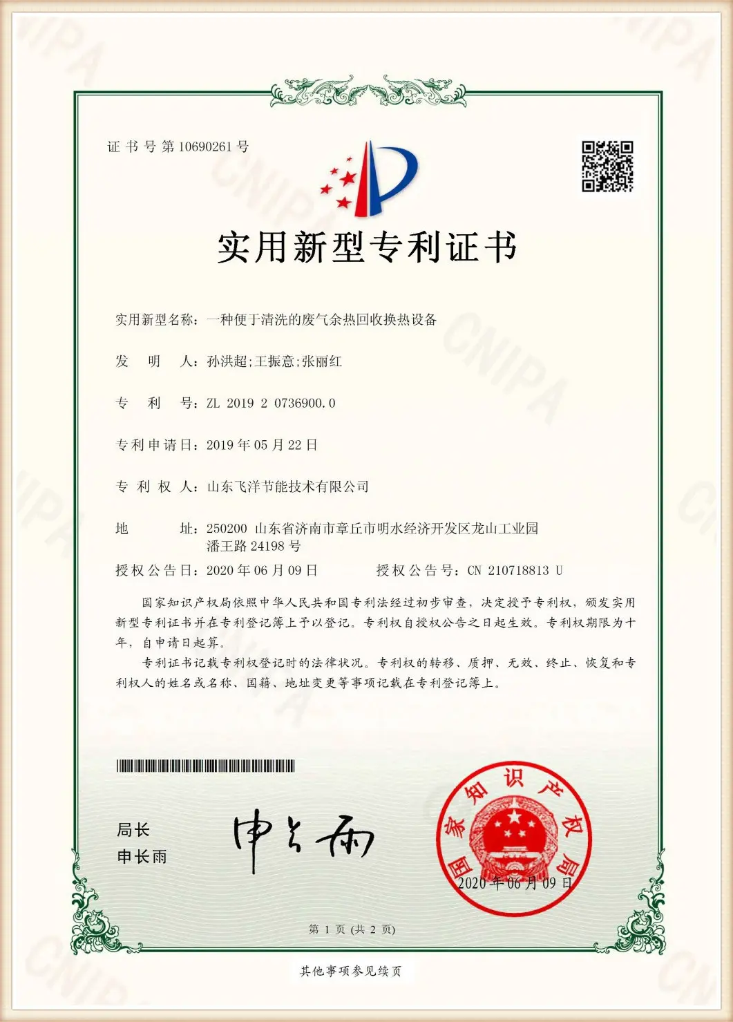
Our commitment to rigorous testing and international quality standards.
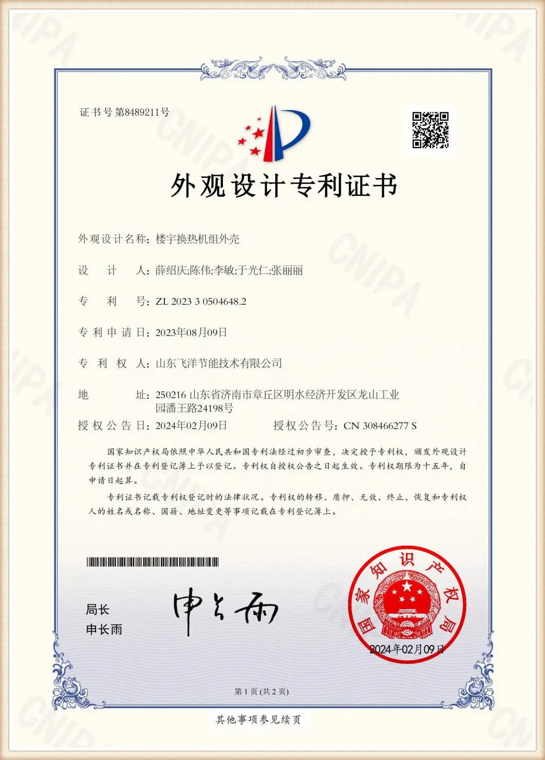
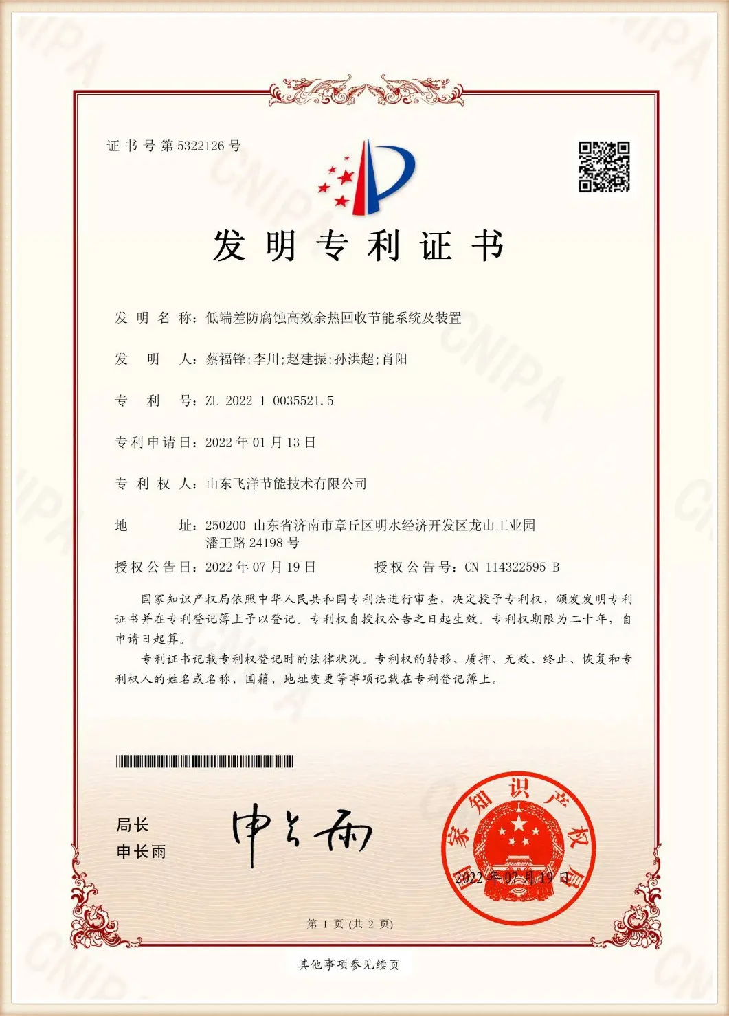
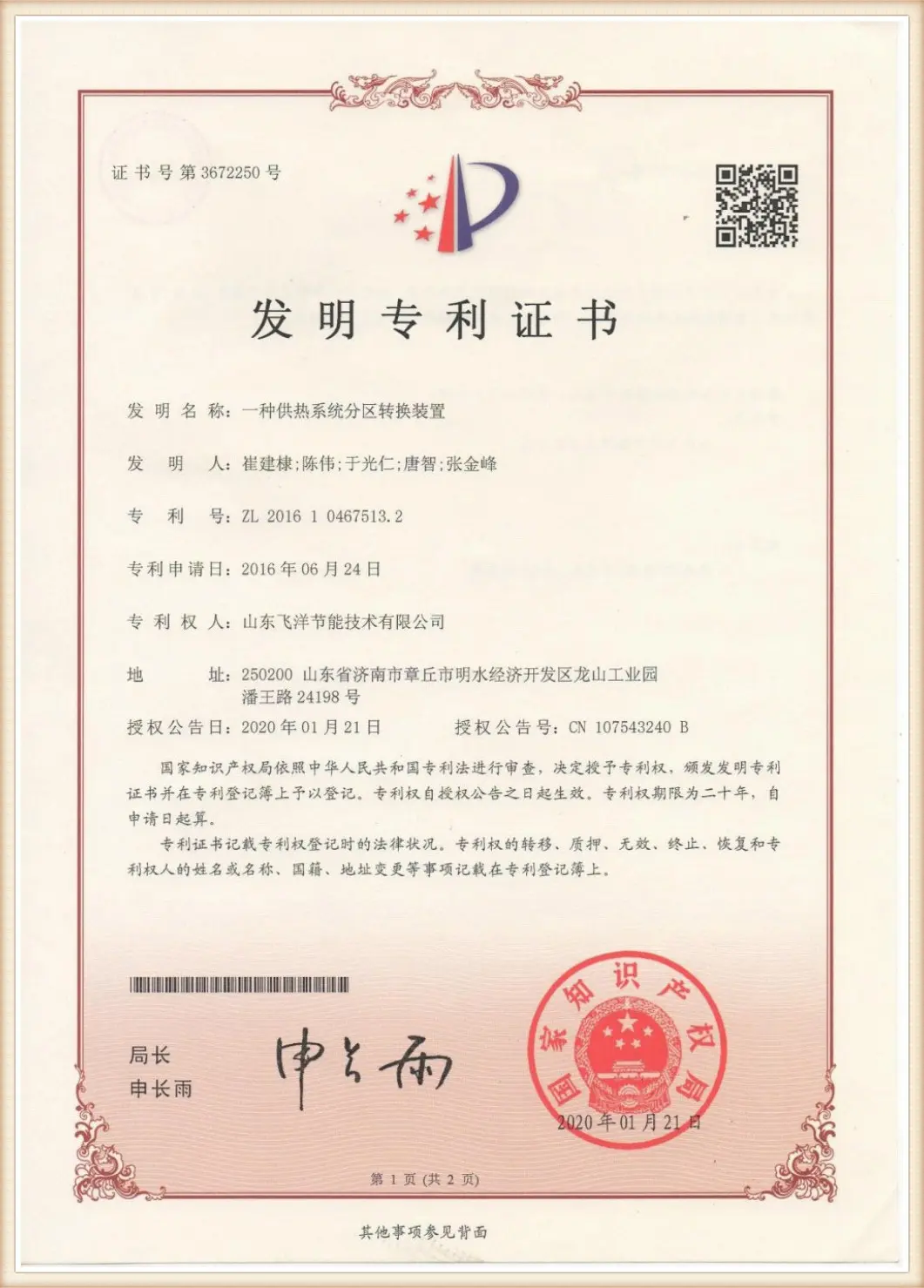
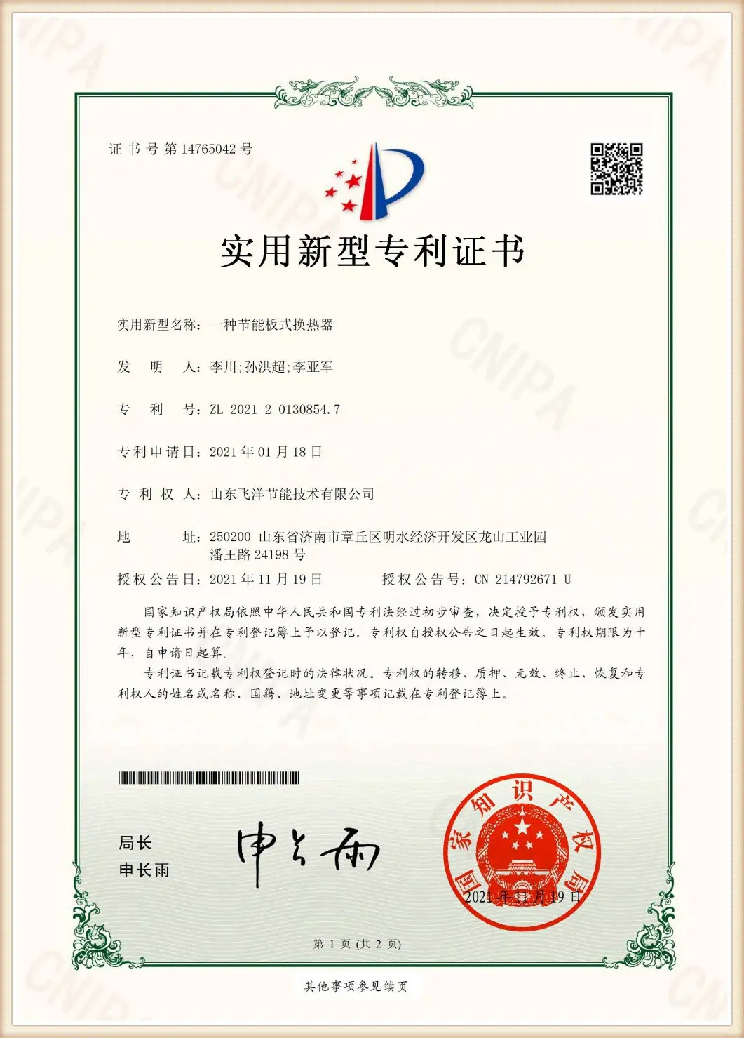
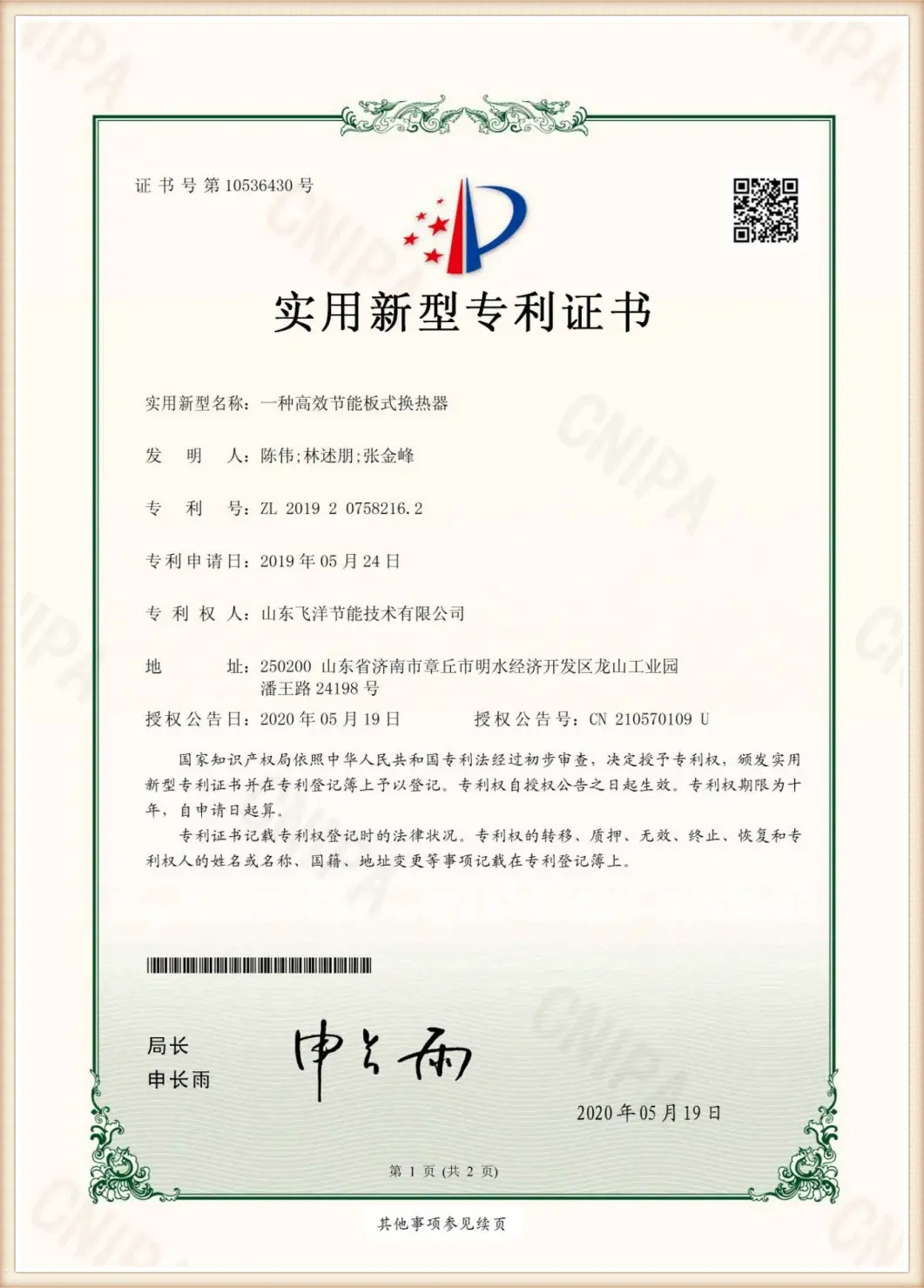
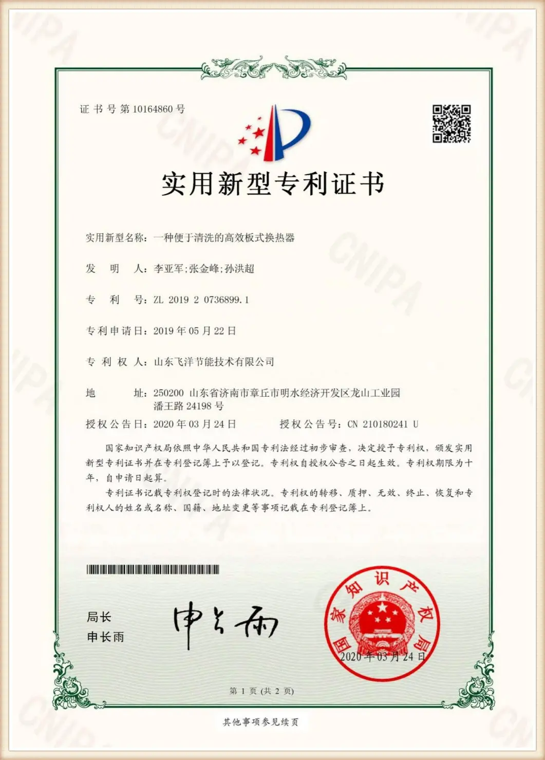
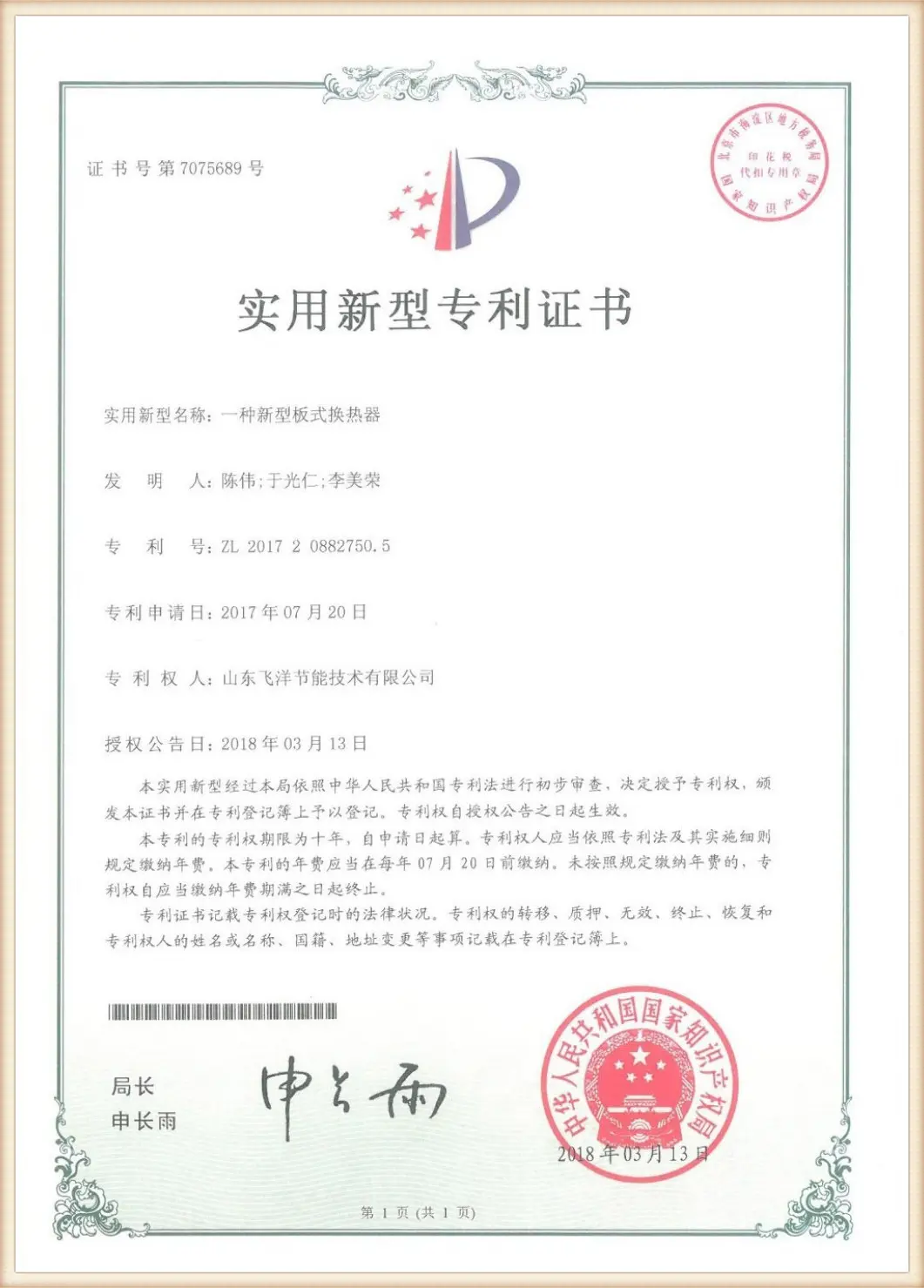



Customized engineering design documentation for regional installations and compliance.
Purchasing raw industrial components without verified engineering support poses significant operation risks. Flotte protects your project with comprehensive engineering documentation, including thermal design calculations, stress analysis, and material certification records. Our global technical support team assists in translating and aligning these specifications with local requirements, ensuring a smooth installation and commissioning process.
Our core range of highly engineered thermal systems and concentration equipment.
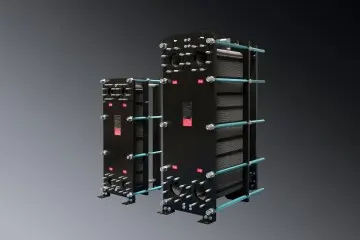
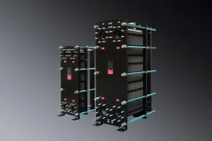
Optimized for efficient liquid-liquid and liquid-vapor heat transfer. Features a modular plate pack for easy expansion and cleaning.
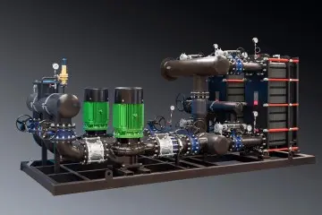
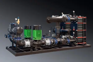
An integrated heating solution designed for municipal heat source interfaces, equipped with smart regulation valves.
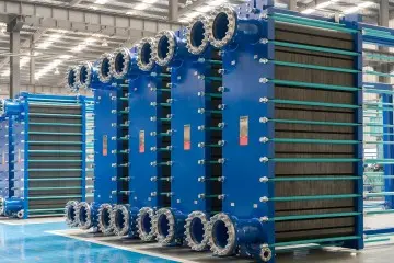
Combines precision pressure regulation with high-efficiency heat transfer, ideal for primary energy distribution networks.
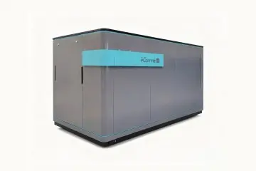
Specifically engineered for HVAC configurations, optimizing energy consumption in commercial and high-rise structures.
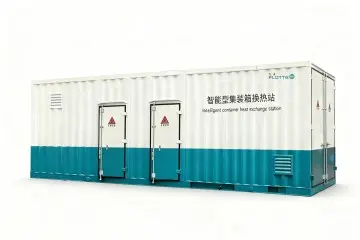
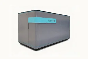
A compact, self-contained heating solution housed in a protective enclosure, suitable for outdoor installation.
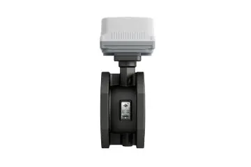
Maintains dynamic hydraulic balance across individual risers, ensuring uniform heat distribution throughout the network.

A high-precision sensor array providing real-time ambient data to smart district heating control centers.
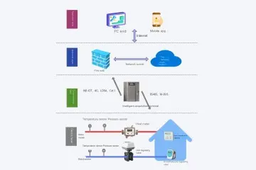
A smart monitoring platform that analyzes grid parameters and adjusts flow rates to eliminate overheating and save energy.
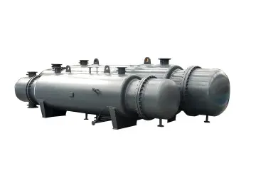
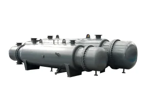
Heavy-duty thermal design for high-pressure, high-temperature industrial processes requiring robust performance.
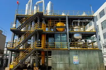
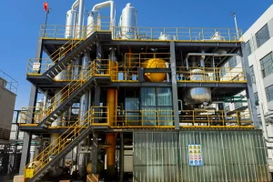
Designed for industrial concentration and concentration tasks, achieving steam utilization through multi-stage heat reuse.
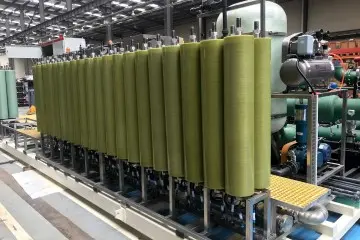
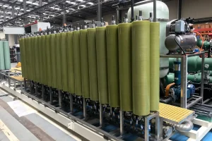
Advanced liquid purification and concentration setup, utilizing specialized membranes to process high-salinity industrial wastewater.
Expert answers to common engineering questions regarding sizing, materials, and operation.
Select a product to view technical specifications, drawings, and engineering options.
 Flotte Energy