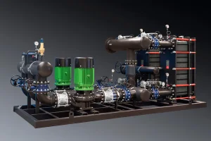
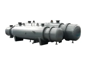
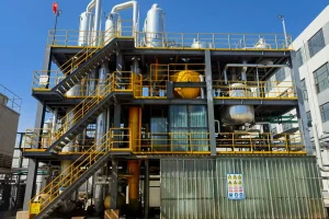
Discover our signature systems engineered for district heating, desalination, and modular industrial HVAC systems.
An in-depth analysis of structural thermodynamics, mechanical diagrams, and Chinese manufacturing excellence for global industrial engineers and procurement heads.
A spiral heat exchanger (SHE) is a highly compact, exceptionally efficient thermal transfer apparatus. Unlike traditional shell and tube configurations, a spiral heat exchanger consists of two concentric metal sheets wrapped around a central core to form two distinct spiral channels. As illustrated in standard mechanical diagrams, the hot medium flows through one channel, while the cold medium flows through the adjacent channel. This architectural geometry achieves a true counter-current flow pattern, optimizing the Mean Temperature Difference (LMTD) and facilitating maximum energy recovery.
When examining a technical spiral heat exchanger diagram, engineers will observe the following core structural components:
The true brilliance of the spiral configuration lies in its self-cleaning mechanism. The single-passage structure dictates that any local accumulation of solids or scaling results in a localized reduction in channel cross-sectional area. According to fluid dynamics principles, this constriction triggers a localized velocity increase, producing a high shear stress that flushes away the deposits.
The fluid circulation depicted in a spiral heat exchanger schematic varies depending on the thermodynamic state of the media. Designers classify these configurations into three primary types:
In liquid-to-liquid heat transfer diagrams, both channels are sealed at alternate ends using specialized welding techniques. The flow path is 100% counter-current. The hot fluid enters at the center header and moves outward to the periphery, while the cold fluid enters from the outer shell and moves inward to the core. This setup is highly effective for heavy, viscous liquids, sludge-laden slurries, and organic waste fluids.
For vapor condensation or boiling applications, the diagram shows a wide vertical flow path for the vapor phase to handle high volumetric flows and minimize pressure drop. The cooling liquid flows in a spiral path, while the vapor enters from the top dome, passes vertically through the spiral channel in cross-flow, and exits as liquid condensate at the bottom.
As a global hub for industrial metallurgy, China has established itself as the leading exporter of custom heat transfer equipment. By choosing a qualified Chinese manufacturer like Flotte, global companies gain major strategic advantages:
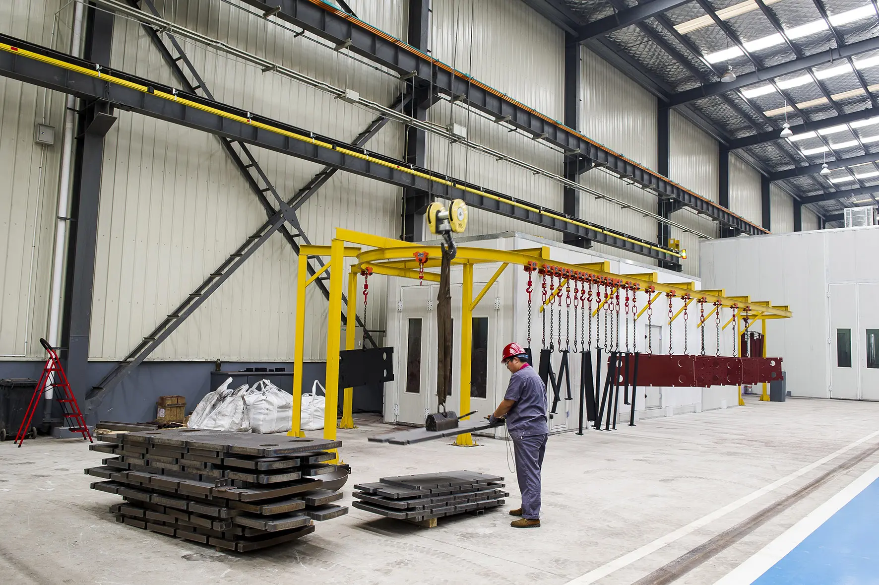
Established in 2013 with a registered capital of 101 million yuan, and inheriting the technological heritage of Flotte Thermal Engineering founded in 1995, Flotte Energy Saving Company brings three decades of technical expertise. Operating from a modern 70,000 m² facility with over 300 skilled professionals, Flotte achieves an annual output of 4,500 heat exchange units and water systems, translating into a powerful capability to fulfill large-scale global procurement orders efficiently.
Spiral heat exchangers are widely implemented in demanding settings where conventional plate-and-frame or shell-and-tube heat exchangers fail:
Why engineers and system integrators trust Flotte Energy Saving Company for industrial heating and water treatment.
Our optimized channels achieve 2-3 times higher heat exchange efficiency than standard designs, resulting in smaller footprints and lowered installation costs.
Covering 8 primary industrial domains, including central heating and municipal water treatment, we match diverse regional regulations and local compliance requirements.
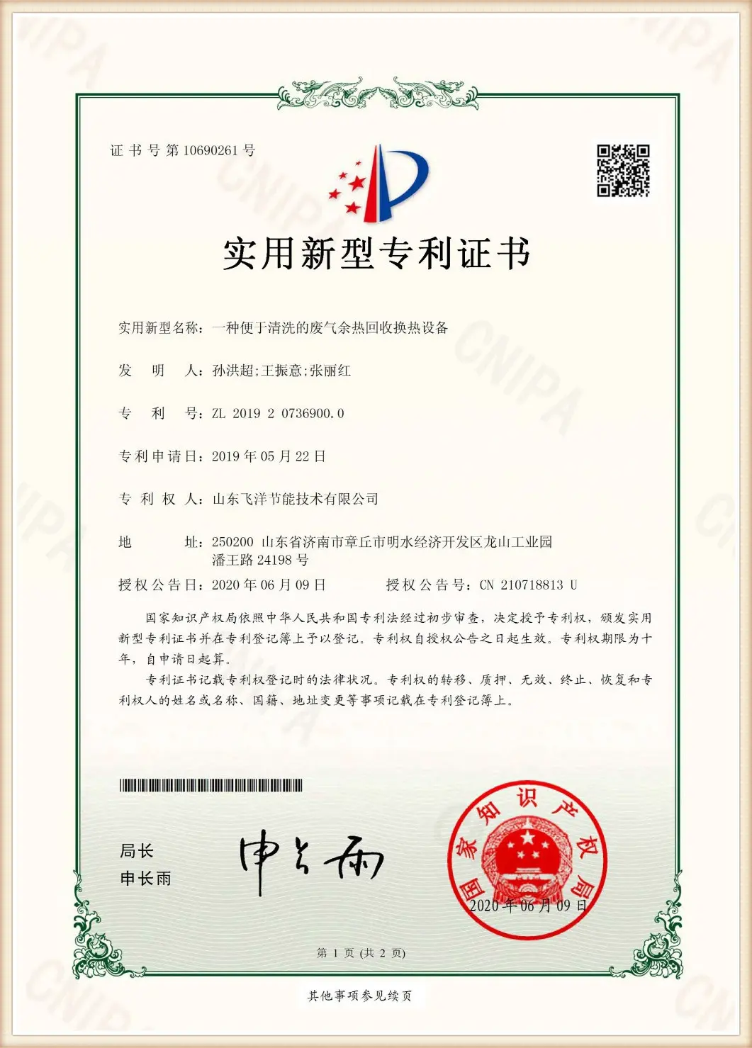
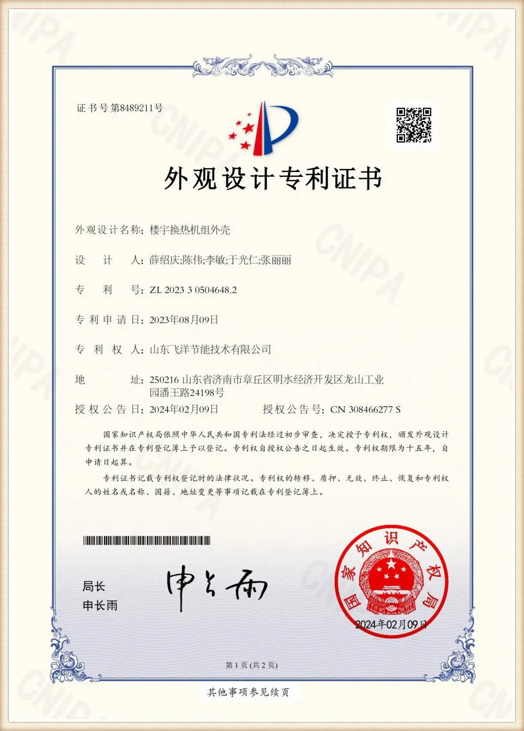
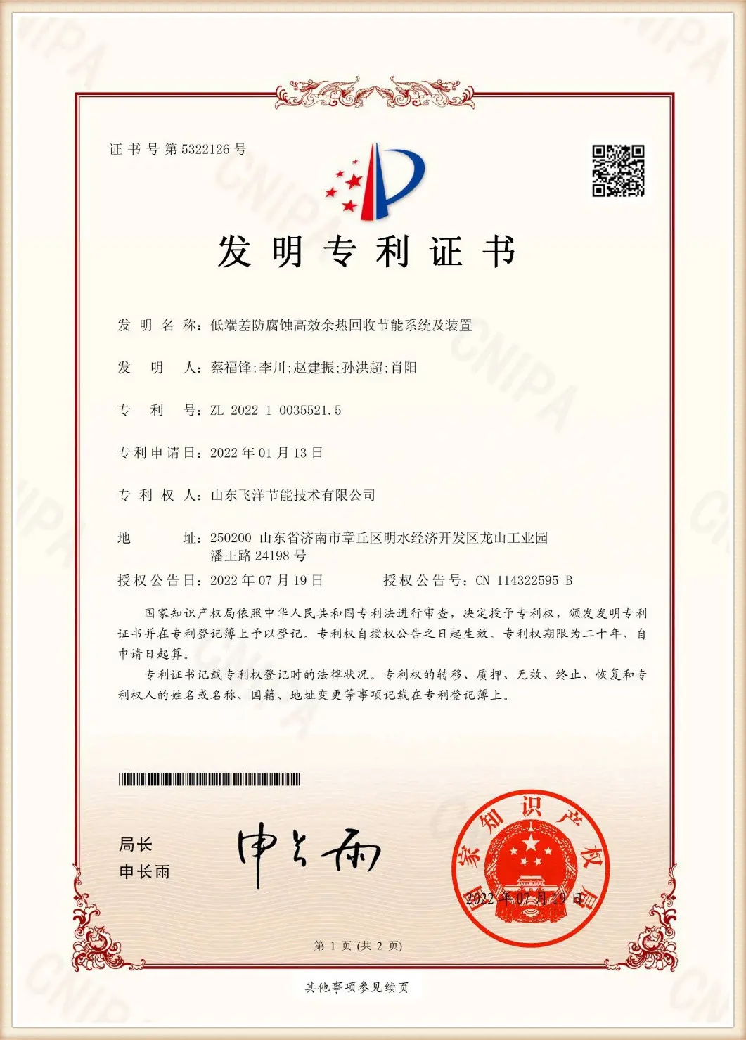
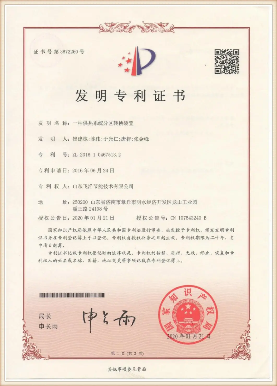
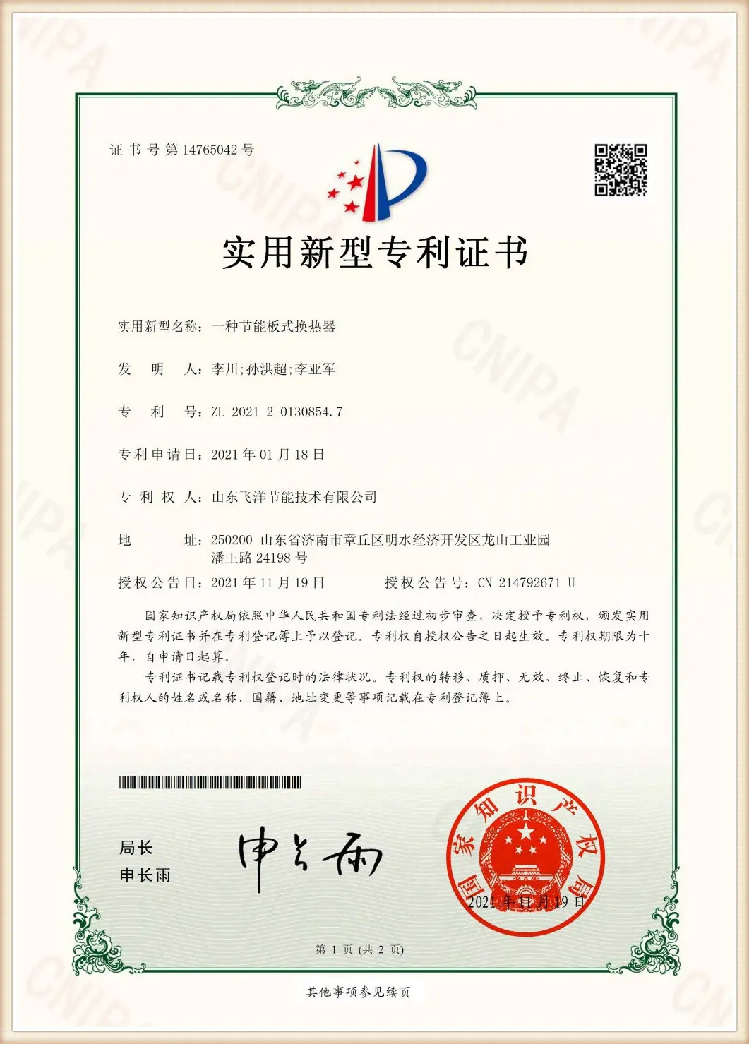
Fully certified under ISO9001:2015, ISO14001, and ISO45001. Our pressure units carry the official safety registrations and national certifications.
From thermal calculation models to localized shipping documentation, our international engineers guide you through layout configuration, installation, and startup.
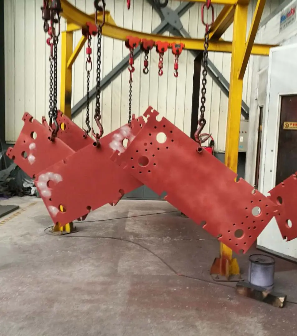
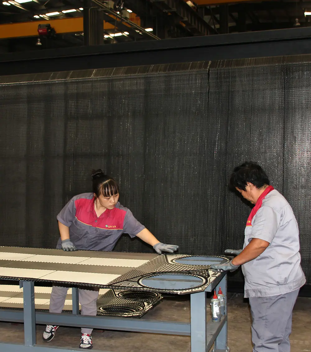
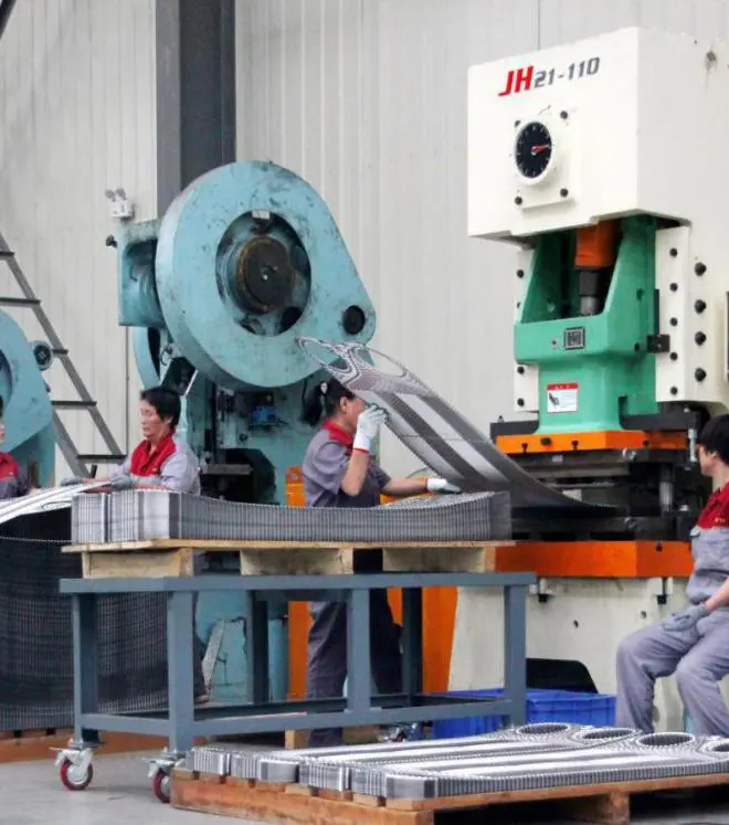
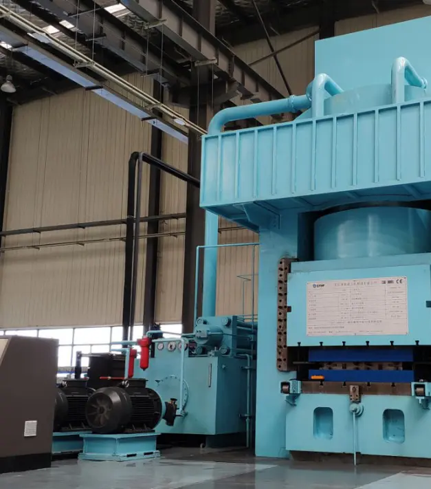
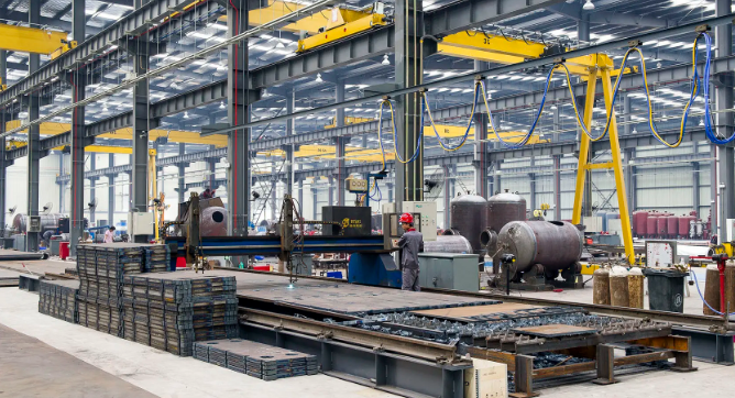
Every thermal element undergoes rigorous structural fabrication stages to meet pressure safety benchmarks.
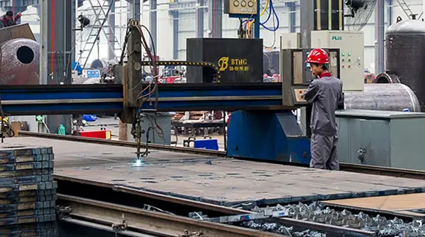
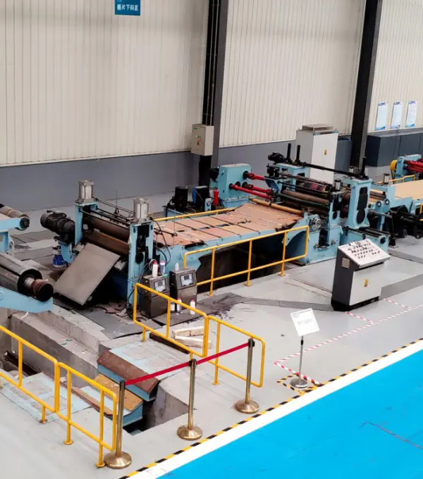
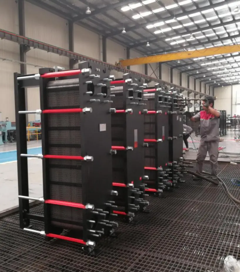
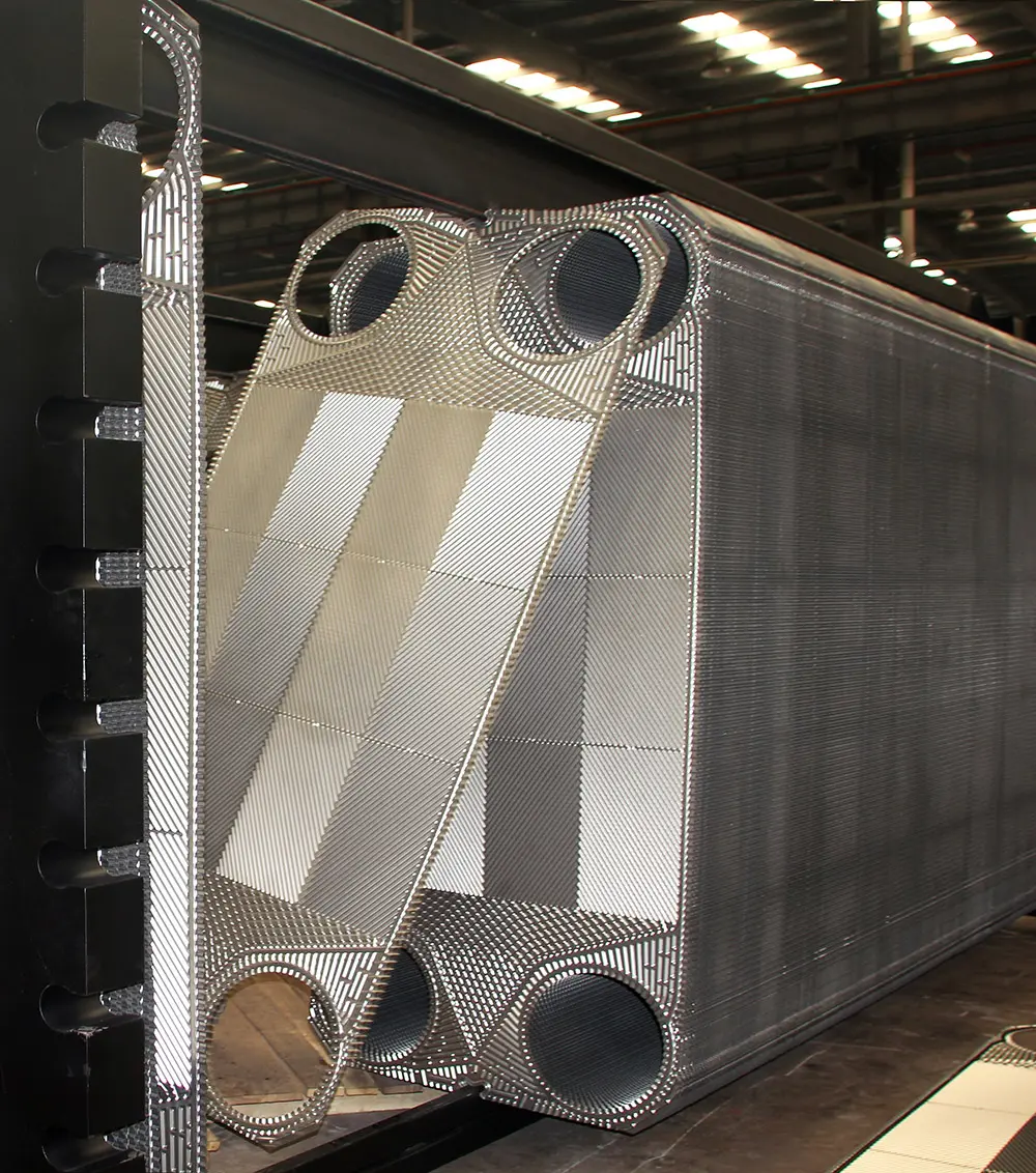
In industrial procurement, selecting the right spiral heat exchanger requires checking several mechanical parameters shown in technical diagrams:
To ensure stability under high operational pressures, designers weld spacer studs at structured intervals along the plate. A detailed diagram specifies the stud density, spacing, and weld profile. Incorrectly placed or poorly welded studs can cause plate deformation and channel collapsing under high differential pressures.
Although spiral heat exchangers are widely known for their self-cleaning performance, periodic maintenance remains essential for maximum operational longevity:
For closed, fully welded spiral exchangers, chemical cleaning is the preferred method. By reversing the fluid pumps and circulating targeted descaling solvents through the spiral path, users can dissolve calcium deposits, metal oxides, and bio-films without structural disassembly.
For removable-cover spiral units, engineers can unbolt the covers to expose the spiral channel faces. A high-pressure water jet can then easily remove compacted biological sludge or mineral scales.
Spiral heat exchangers offer a significantly higher heat transfer coefficient and a smaller physical footprint. Their single-passage design is highly resistant to clogging and fouling, making them perfect for handling high-solid slurries and wastewater where shell-and-tube units often clog.
Yes. While standard plate exchangers are limited by rubber gasket materials, fully welded spiral configurations can handle temperatures up to 400°C and design pressures exceeding 4.0 MPa, depending on plate thickness and stud spacing.
For clean media or light condensation, channel spacing of 5mm to 10mm maximizes efficiency. For slurries, fibrous pulps, or fluids with high scaling risk, spacing from 12mm to 25mm is recommended to ensure smooth passage.
Leading exporters like Flotte provide certifications conforming to ASME Section VIII Division 1, CE-PED for the European market, GB150 for domestic Chinese standards, as well as marine class approvals like DNV-GL, ABS, or LR.
Operating under a strict quality management system to deliver high-quality thermal equipment worldwide.
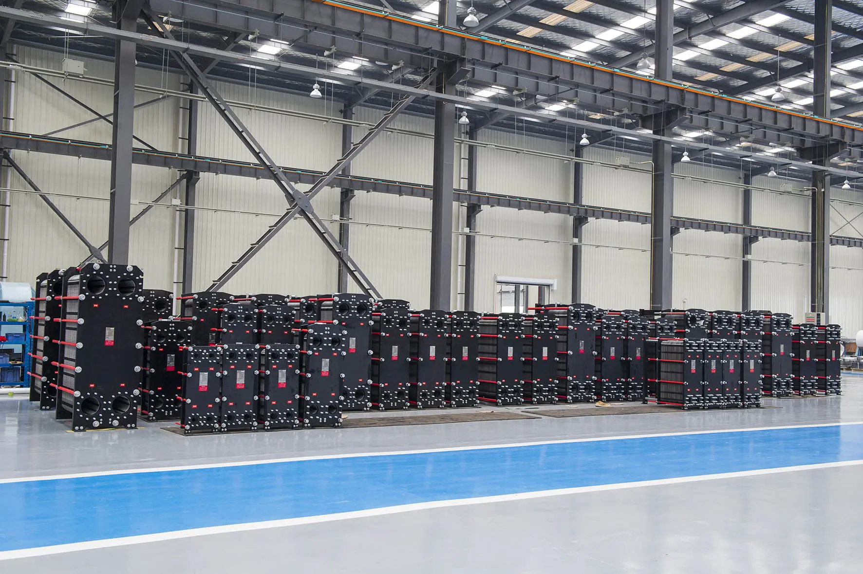
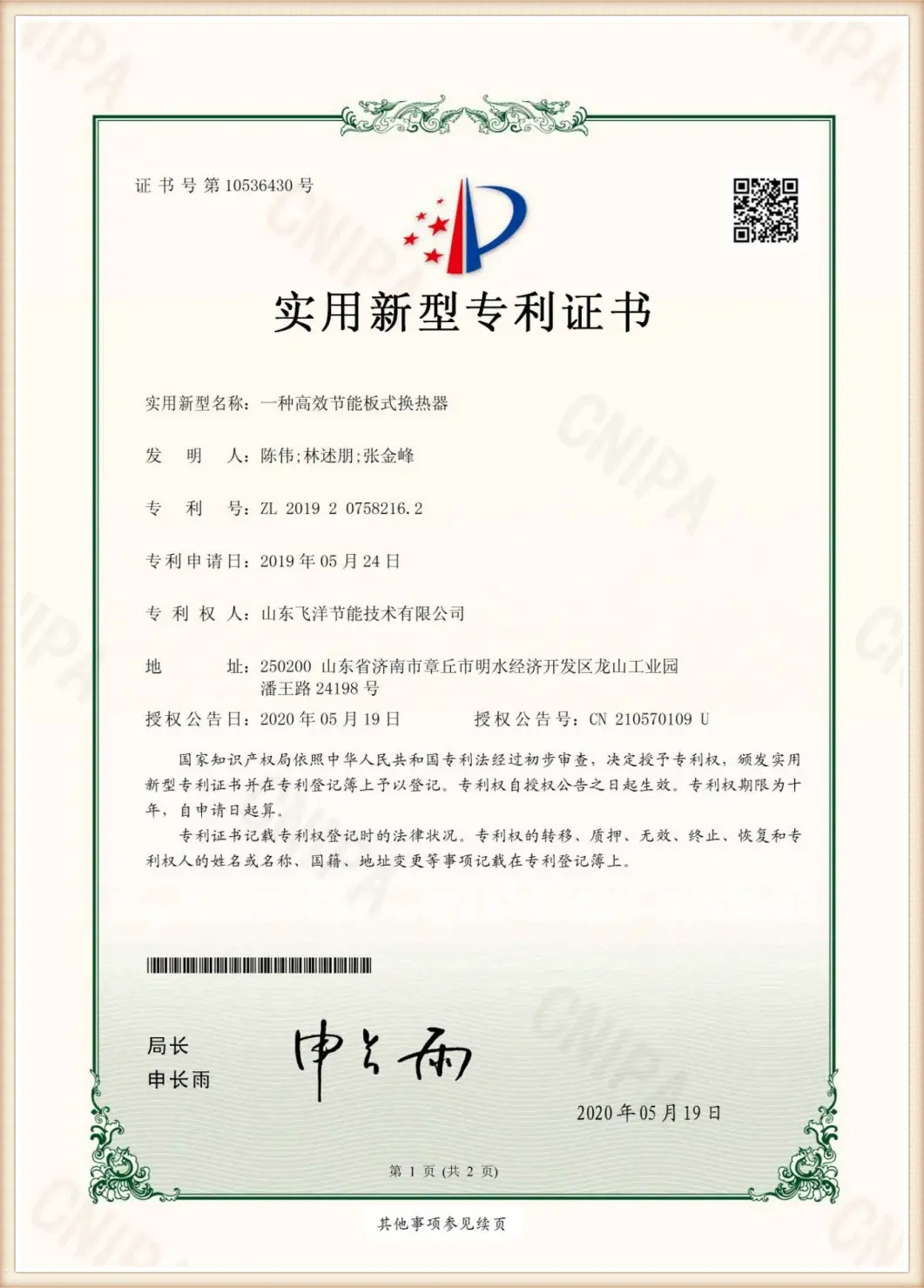
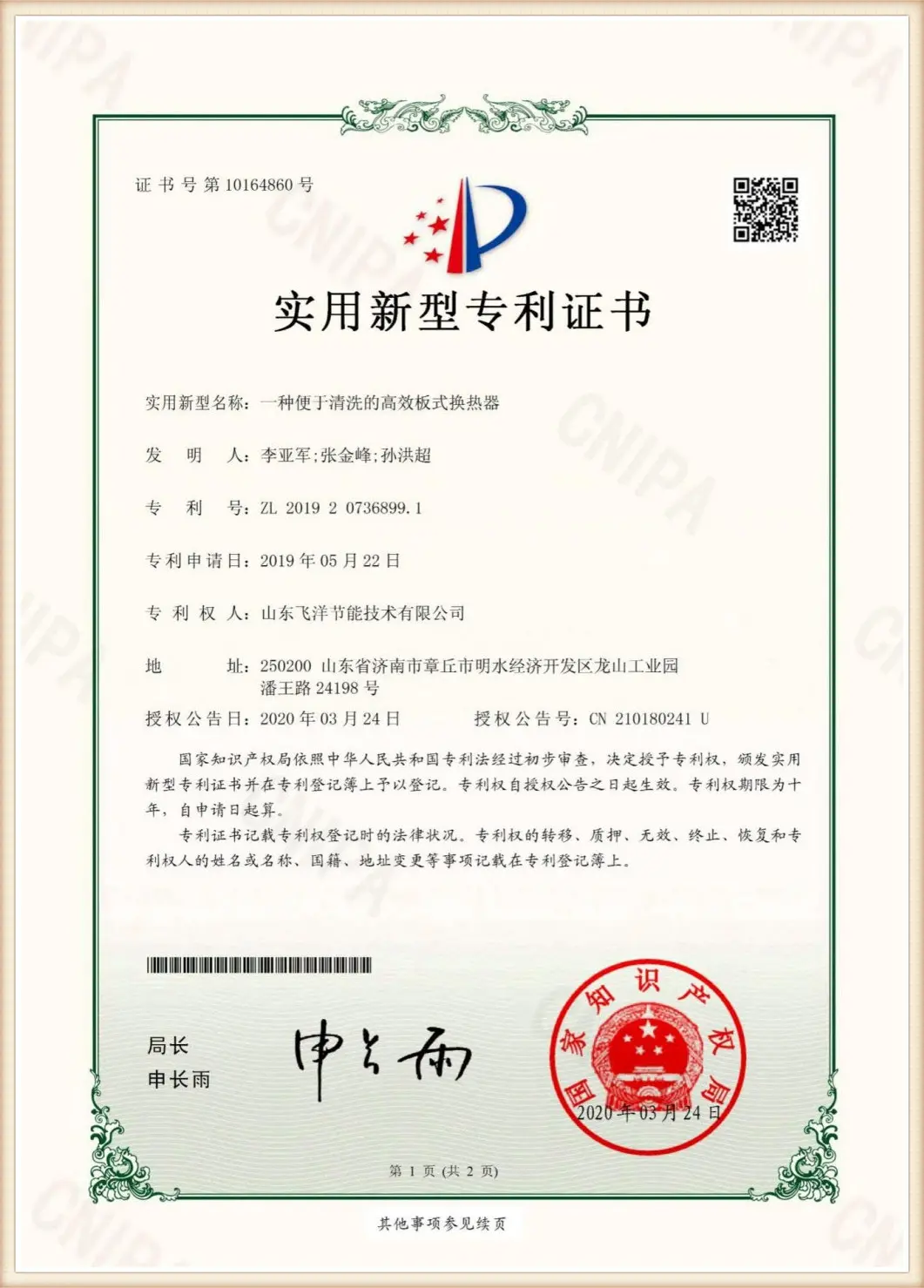
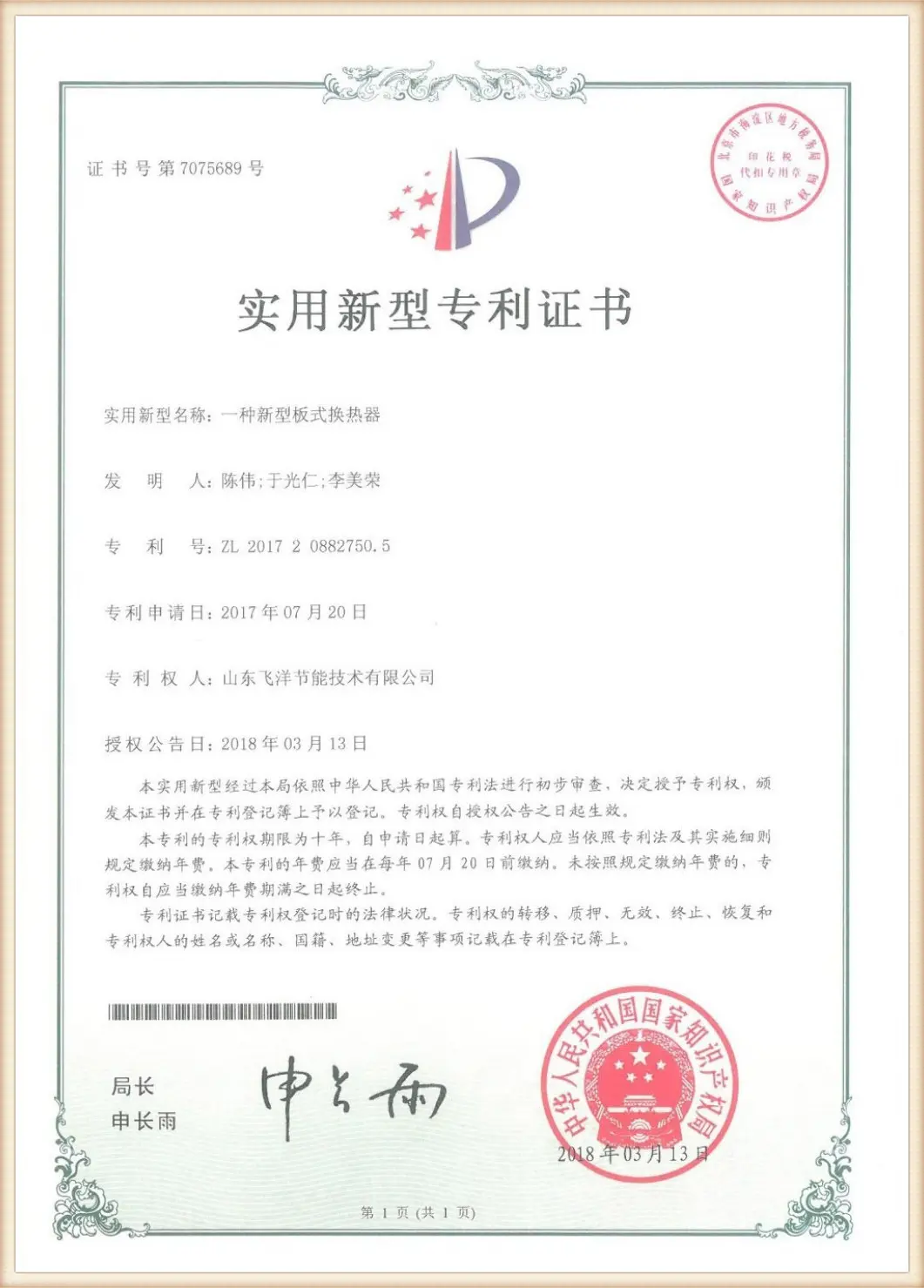
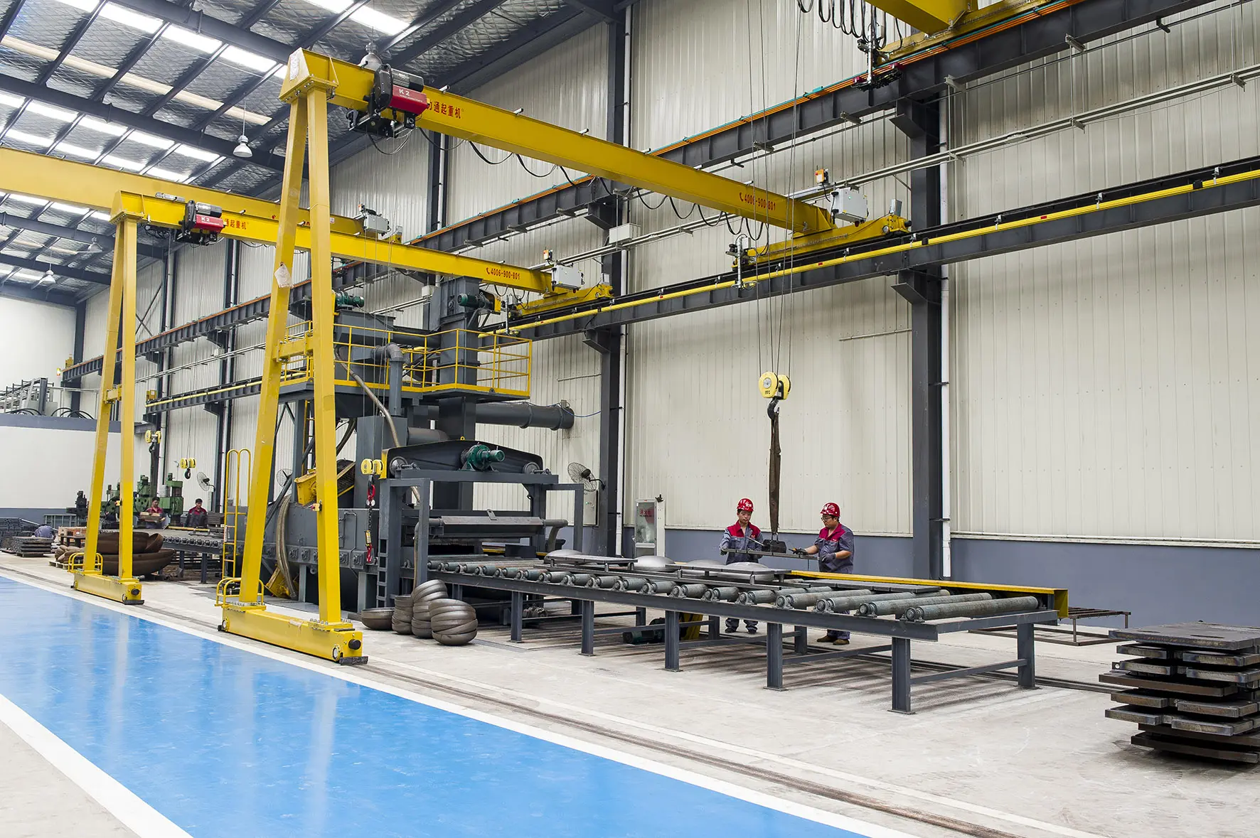
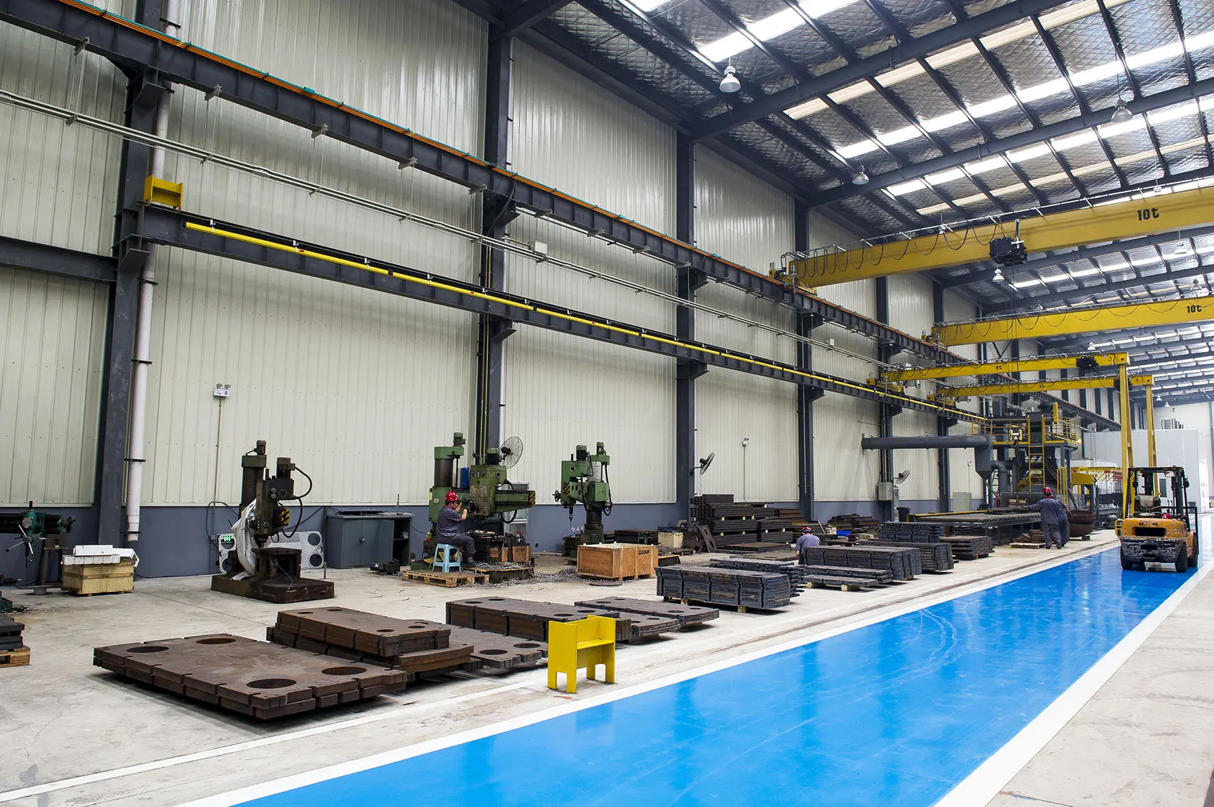



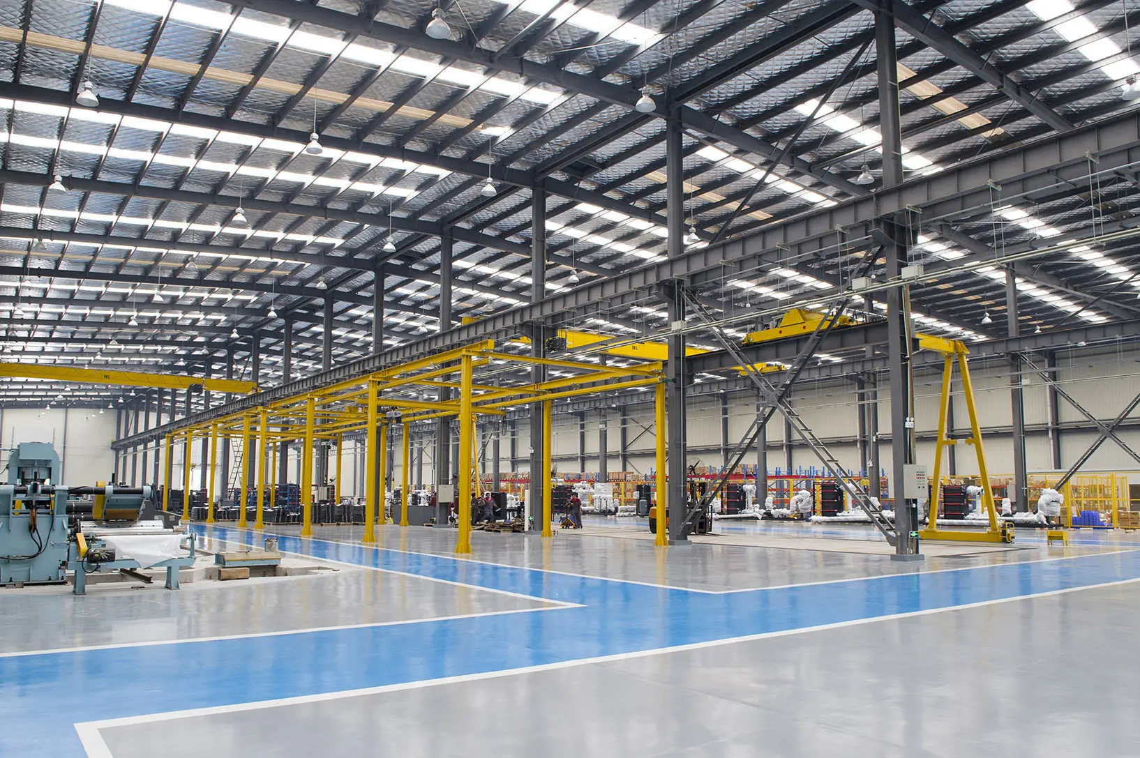
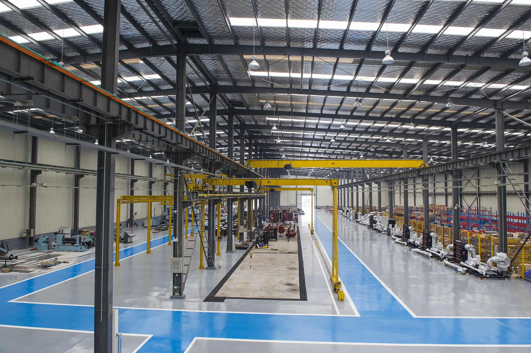
From heavy chemical plant evaporation systems to high-efficiency building HVAC units, Flotte supplies customized options for all requirements.
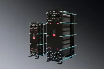
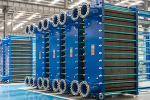
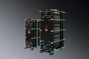
Versatile, gasketed heat exchangers for process liquids and steam condensation.
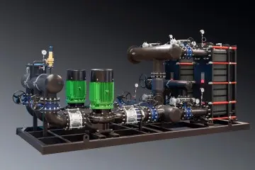
Fully automated, integrated heating solution equipped with smart PLC regulators.
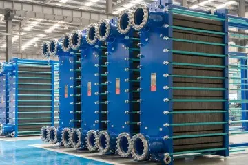
Built for municipal district heating grids, integrating reliable control valves.

Energy-saving structural interfaces optimized for large commercial complexes.
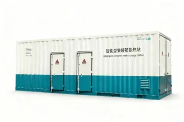
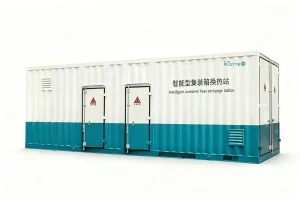
Self-contained weatherproof thermal exchange units for outdoor installations.
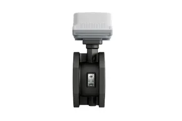
High-precision fluid control hardware for secondary heating circuits.

High-precision smart sensors used in municipal feedback loops.

Cloud-based software suite coordinating valves and flow rate distributions.
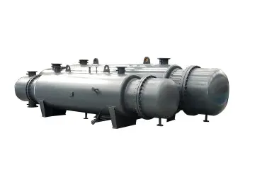
Traditional heavy duty pressure vessel systems for refinery and chemical processes.
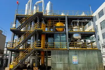
Engineered for concentration, crystallization, and ZLD wastewater systems.
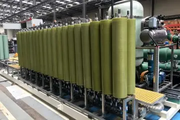
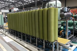
Advanced microfiltration/RO assemblies for high purity separation steps.
Browse our broader range of heat exchangers, balance valves, and evaporation systems designed to optimize energy efficiency.
 Flotte Energy